HW9
Problem Statement
Explain how Third Harmonic Sampling works and explain how a Quadrature Sampling Detector works too.
Solution
When considering the properties of an oscillator's wave it is important to include its Fourier series. From electronics last year we were able to construct a square wave by summing multiple sine waves with the same basic or rather the summation . As indicated in the problem statement we are interested in the third one, or rather the third harmonic:
Comparing this to our original function of we have three times the frequency or rather a third of the period.
For the soft rock 40 radio this property is used to maintain a cost effective ham radio while achieving a high quality signal output. It is important for the mixer to have a very high frequency but oscillators that operate at the frequencies required are very expensive so a cheaper oscillator may be purchased while maintaining the function of the radio.
Unfortunately their is loss attributed to increasing the oscillator frequency. Because our amplitude in the series is reduced by 1/n for each harmonic we are only at 1/3 the amplitude for the third harmonic. Rather this is a loss.
In electronics we built a radio that required both the real and imaginary parts of the signal to go through the mixer. This requires us to mix with a sine and cosine wave simultaneously in different parts of our circuitry. To do this it is necessary to use a QSD (Quadrature Sampling Detector). This can be built with either diodes and transformers or transistors and transformers. I believe we attempted both designs and finally settled on the transistor schematic.
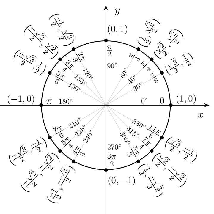
The concept that allowed me to understand the QSD had to do with the unit circle.

(I apologize for the large size, I didnt bother resizing it.)
As the oscillator signal is sent through the QSD it in turn rotates around the unit circle. First it is at 0° then it rotates to 90° then to 180° and finally to 270° before returning to 0°. In my mind their is a switch opperating like a clock hand in the center of the circle and wires to hook up with it at each of the axis'. The signals received during these rotations then sent out to the two mixers. The 0° and 180° are sent out to the cosine wave and the 90° and 270° are sent to the sine wave. Although it is only a matter of phase as to which signal they are to mix with and can be adjusted as to the designers preference.


