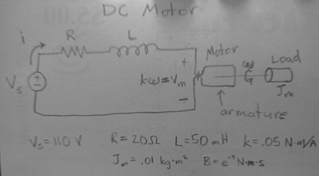
Laplace transforms:DC Motor circuit
Problem
Find the steady state current i(t) through a DC motor represented by a series R-L-Motor circuit. The resistance (R) is from the armature winding. The inductance (L) is the equivalent inductance of the wire coil (which turns by current flowing through the coil in a permanent magnetic field). Jm is the combined moment of inertia of the armature and load. B is the coefficient of friction. The motor has input current i(t) and output angular velocity ω(t). Let v(t) = 110u(t)V, R = 20Ω, L = 50mH, k = 0.05N*m/A, Jm = 0.01 kg*m2, and B = e-4N*m*s.
Solution
Since some of the elements of a motor are not typical circuit elements, we must solve this problem using Laplace transforms.
The torque is proportional to the armature current.
Similarly, relating mechanical (T(t)ω(t)) and electrical (vm(t)i(t)) power, the conservation of energy requires the same proportionality between the voltage across the motor (vm(t)) and the angular velocity (ω(t)).
We want to find the Laplace transfer function of the motor, and we define it as follows.
Summing the voltages around the series circuit gives us our differential equation.
Take the Laplace transform.
If we let i(0) equal zero, the transformed differential equation gives us Equation *1*.
Repeat the process with the analogous mechanical differential equation. Here Jm is the moment of inertia of the combined armature, shaft, and load. B is the coefficient of friction.
Transforming yields the following.
Recall T(t) = k i(t), and so T(s) = k I(s). Again let ω(0) = 0. This gives us Equation *2*.
Solve Equation *2* for I(s) and substitute that into Equation *1*.
Solve this equation for Ω(s), some simplification steps are skipped here. Equation *3*
Final Value Theorem
Now in order to apply the final value theorem we let Vs(s) = K/s. The s's in the limit definition and in K/s cancel. We can now see ω in steady state.
Take Equation *2* and Equation *3* and this time solve for I(s). This will get us a form of the final answer in the s domain.
Finally was can apply the final value theorem to see what our steady state response will be for the armature current.
Answers
Of interest are the ω(∞) and i(∞), found by plugging values into the steady state solutions above.
Bode Plot
Break Points and Asymptotes
The transfer function of the motor voltage over the voltage source.
Now we need to plug in the given values to find our transfer function and characteristic equation.
At zero's we would see an increase of 20 dB/decade, but the numerator has no zeros. At poles we see drops of 20 dB/decade, and we see 2 such drops at the appropriate values of 1.8 and 400 on the frequency graph. You can find the starting point on the dB scale by evaluating the transfer function when s=0 and taking 20log10(H(0)) of this value. In this case we'd have H(0)=2000/1.8*400=2.71. So our expected starting value should be 20log(2.71)=8.67, and it appears to be correct. If the graph was larger, it would be apparent that we have asymptotic behavior going down at 40 dB/decade to the right of 400 radians/second. This is because 400 is the largest root in the denominator of the transfer function and as s goes to infinity the bode plot will never go above that asymptote.
Convolution
For this we need the inverse Laplace transform of our H(s).
First use partial fraction expansion, or your fancy calculator, to expand the transfer function.
I found A = 5.0237 and B = -5.0237
Now we can take the inverse transform.
State Equations
First we need to write our state equations, which are rearranged forms of our original differential equations. The state variables will be current (i) and angular velocity (ω).
The following is an alternate way to represent the dc motor circuit as a matrix system of equations.
Reviewed by Andrew Hellie


![{\displaystyle \Omega (s)={\mathcal {L}}[\omega (t)]/v_{s}(s)}](https://wikimedia.org/api/rest_v1/media/math/render/svg/636ab7f754f600f7c51b29ff144cfebb09a2c13f)


![{\displaystyle I(s)={\frac {(J_{m}s+B)}{k}}\left[{\frac {\frac {k}{J_{m}L}}{s(s^{2}+({\frac {B}{J_{m}}}+{\frac {R}{L}})s+{\frac {RB+k^{2}}{J_{m}L}})}}\right]K={\frac {{\frac {s}{L}}+{\frac {B}{J_{m}L}}}{s(s^{2}+({\frac {B}{J_{m}}}+{\frac {R}{L}})s+{\frac {RB+k^{2}}{J_{m}L}})}}K}](https://wikimedia.org/api/rest_v1/media/math/render/svg/eefa3c7dd21a8ba82f933df00c310773a3b0c1a2)


![{\displaystyle h(t)={\mathcal {L}}^{-1}\left[{\frac {5.0237}{s+1.844}}-{\frac {5.0237}{s+399.956}}\right]}](https://wikimedia.org/api/rest_v1/media/math/render/svg/4bef5e4e8e0d798baa4778989b3c81146a7fa90c)
![{\displaystyle h(t)=[5.0237e^{-1.844t}-5.0237e^{-399.956t}]u(t)\,}](https://wikimedia.org/api/rest_v1/media/math/render/svg/62ec4f7e5e10960764b51e5e01926dc5117c8c12)


