Third harmonic sampling and QSD - HW9
Max Woesner
Homework #9 - Third harmonic sampling and QSD
This page describes how third harmonic sampling and a QSD (quadrature sampling detector) work.
References:
SoftRock-40 SDR interest group
FlexRadio SDR-1000 QEX articles
Third Harmonic Sampling
Third harmonic sampling is used in some applications, such as the SoftRock-40 software defined radio, to divide the local oscillator frequency by three.
Consider the simple representation of part of a software defined radio below.
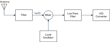
The local oscillator can be defined as , giving us a square wave. Note that
The output voltage of the radio, or is
Now can be written as the series
We are interested in the third harmonic term, or
This frequency is three times that of . Note that the period decreases by a factor of three.
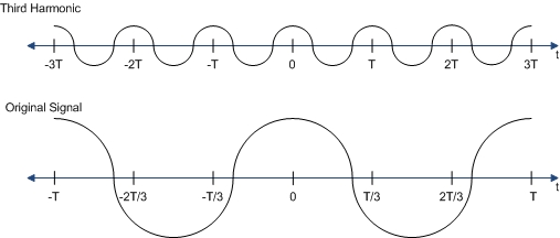
We can use the third harmonic to drive the mixer in the radio at a frequency three time that of the local oscillator.
The advantage of using the third harmonic rather than using a higher speed oscillator is that it costs less to buy both a lower frequency oscillator as well as the parts that are driven by the oscillator.
The disadvantage is that there is some loss in the signal when the third harmonic is used, specifically
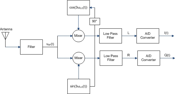
We can now apply the same concept to a radio with parallel doubly balanced mixers. The radio could be represented such as in the diagram below.
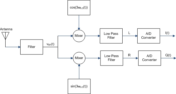
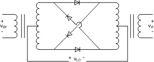
We could use a mixer like this one.
Quadrature Sampling Detector
If you read the above section about third harmonic sampling, then you might be wondering how we input both and into the parallel mixers. The answer is that we can use a quadrature sampling detector, or QSD.
The local oscillator is directly fed to the lower-channel mixer and is delayed 90 to feed the upper-channel mixer. The upper channel provides the in-phase signal , and the lower channel provides the quadrature signal .
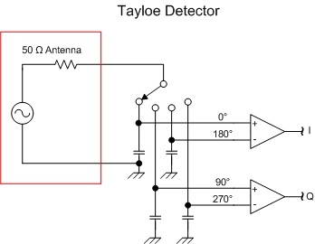
A common QSD is the Tayloe detector, named after designer Dan Tayloe. The Tayloe detector can be thought of as a four-position rotary switch. The switch revolves at the same rate as the carrier frequency. Each of the four switch positions is connected to a sampling capacitor, and the 50 ohm antenna impedance is connected to the rotor. Each capacitor will track the carrier's amplitude for exactly one-quarter of the cycle since the switch rotor is turning at exactly the RF carrier frequency, causing the switch to sample the signal at 0°, 90°, 180° and 270°. If the switch is off, each capacitor will hold its value for the remainder of the cycle. The 180° and 270° outputs carry redundant information with the 0° and 90° outputs respectively. Therefore the 0° and 180° outputs can be summed differentially to produce the in-phase signal (I). Similarly, the 90° and 270° can be summed to form the quadrature signal (Q).
