AM vs FM Modulation
FM Modulation
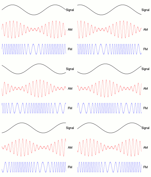
Frequency modulation is achieved by changing the frequency of the carrier wave in response to the amplitude of the modulated signal. A higher-frequency carrier represents larger amplitude, and a lower frequency represents a lower amplitude. This is opposed to AM which changes the amplitude of the carrier wave in response to the modulated signal.
The advantage of FM is a much higher signal integrity over AM because the frequency of a signal doesn't change with distance from source like it does with AM. This means that FM will have the same signal quality right up until its maximum range where the carrier wave is finally overwhelmed by noise and cannot be detected. The disadvantages are a larger bandwidth requirement for the signals since the frequency needs to be able to change within a set range for the modulation to work and the requirement for a more complex receiver since it is much more difficult to demodulate than AM.
There are several methods used to demodulate a FM signal. The most common is a Foster-Seeley discriminator, which uses a tuned RF transformer to convert the frequency changes into amplitude changes. This is done by feeding the FM signal into the center tap of the transformer. If the frequency of the signal equals the tuned frequency of the transformer, the two halves will be in balance and produce 0 voltage. Otherwise, a voltage imbalance is created that is proportional to the frequency.
A lot of newer radios will use a digital signal processor to demodulate FM as this eliminates the need for complex hardware in the receiver (assuming you already have a computer anyways).
AM Modulation
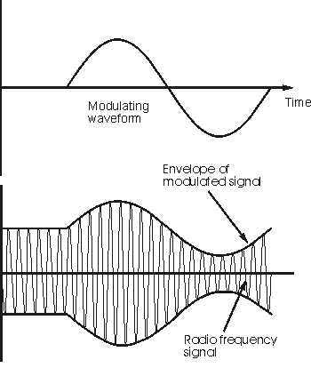
Amplitude modulation (AM) mixes a carrier signal with another signal that will be sent. The result of the mixing the two signals is the sum of frequencies and the difference of the frequencies. The part of an AM signal that is formed by the sum of the frequencies is known as the upper side band and the part formed by the difference of the frequencies is called the lower side band. On a plot, the lower side band looks like the horizontal reflection of the upper side band, together they make the AM signal look like an envelope. The amplitude of the signal to be sent however must be limited so that clipping will not occur. Lets imagine that the amplitude of the signal in the image below is twice as large then the Upperside band frequencies will drop below the horizontal axis causing clippping.
 Image source: http://www.electronics-radio.com/articles/radio/modulation/amplitude_modulation/am.php
To demodulate the signal, it is passed through a circuit with a series diode and a low-pass filter. The diode removes the lower side band then the low-pass filter removes all but the highest frequencies or the peaks. The process of the demodulation returns the original signal. Performing amplitude modulation then demodulation has enabled the desired signal to be successfully sent. AM is popular because the receiver has simple circuitry and is cheap. Unfortunately, AM modulation is the oldest type of modulation and when compared to newer, improved types of modulations, AM is much noisier.
