Consider a simple, transformer with two windings. Find the current provided by the voltage source.
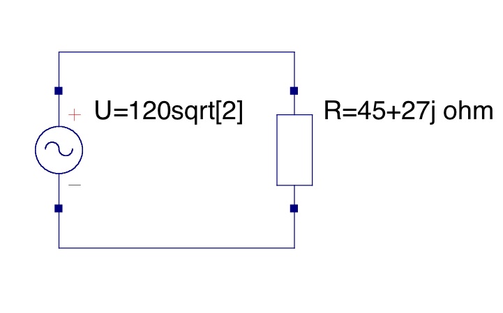
- Winding 1 has a sinusoidal voltage of
 ° applied to it at a frequency of 60Hz.

- The combined load on winding 2 is

Solution
Given:
 and
and 
Substituting  ,
, 
Therefore, 
Now the Thevenin equivalent impedance,  , is found through the following steps:

Since this is an ideal transformer  and
and 
So we can substitute, 

Now, plugging in the given values:


Since this is an ideal transformer, it can be modeled by this simple circuit:
Therefore,  ,
,

Contributors
Christopher Garrison Lau I
Reviwed By
Andrew Sell - Chris, everything looks fine, though I would do some extra formatting if possible to help make the problem flow a little smoother as you read it, and locate the picture a little higher to help bring the solution together.
Tyler Anderson - Looks good.
Read By
John Hawkins
