Chapter 3: Difference between revisions
Jump to navigation
Jump to search
No edit summary |
No edit summary |
||
| Line 4: | Line 4: | ||
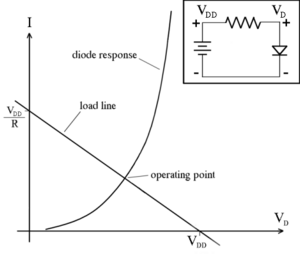
*Because diodes are a nonlinear device, traditional circuit analysis will not work on them. One method of analyze the diodes is to do it graphically. This technique is called Load-line analysis. |
*Because diodes are a nonlinear device, traditional circuit analysis will not work on them. One method of analyze the diodes is to do it graphically. This technique is called Load-line analysis. |
||
**Load-line is only used for dc analysis? |
**Load-line is only used for dc analysis? |
||
*In circuits with multiple diodes, it is not immediately apparent which diodes are on or off. The ideal-diode model assumes that the diode is a perfect conductor with zero voltage drop in the forward direction and an open circuit in the reverse direction. |
|||
#Assume a set of states for the diodes |
|||
#Solve the circuit to find <math>i_D</math> for diodes assumed to be on and <math>v_D</math> for diodes assumed to be off |
|||
#Check to see if <math>i_D</math> is positive for all diodes assumed to be on and if <math>v_D</math> is negative for all diodes assumed to be off. |
|||
Revision as of 12:51, 8 February 2010
- Forward bias occurs when the P-type semiconductor material is connected to the positive terminal of a battery and the N-type semiconductor material is connected to the negative terminal, as shown below. This usually makes the p–n junction conduct. <ref> Wikipedia P-N junction</ref>
- Will the current always flow from the anode to the cathode when the diode is forward biased?
- Because diodes are a nonlinear device, traditional circuit analysis will not work on them. One method of analyze the diodes is to do it graphically. This technique is called Load-line analysis.
- Load-line is only used for dc analysis?
- In circuits with multiple diodes, it is not immediately apparent which diodes are on or off. The ideal-diode model assumes that the diode is a perfect conductor with zero voltage drop in the forward direction and an open circuit in the reverse direction.
- Assume a set of states for the diodes
- Solve the circuit to find for diodes assumed to be on and for diodes assumed to be off
- Check to see if is positive for all diodes assumed to be on and if is negative for all diodes assumed to be off.
References
<references/>


