Single Sideband and the Hilbert Transform
Radio spectrum is a very valuable resource, and should not be wasted, and it is more valuable the closer to DC it is because equipment to use those frequencies is much less expensive. A way to make use of more the the available frequency spectrum is to translate signals from baseband (near DC) to a higher frequency, $f_c$ using frequency translation. This way we can have various different radio stations to choose from, and we don't all have to listen to the same music, etc. The simplest way to do this is to take the audio signal, $m(t)$ and multiply it by $cos(2\pi f_c t)$. This is called double sideband modulation. Modulation is what we call the process of encoding the information on a carrier signal, $cos(2\pi f_c t)$. In general the modulation process takes the audio signal, $m(t)$ and creates a complex function, $g(t) = x(t) + jy(t)$ that is some function of $m(t)$. For example, in double sideband modulation, $x(t) = m(t)$ and $y(t) = 0$. The property of frequency translation shows that the spectrum of the double sideband signal is $1/2M(f-f_c) + 1/2 M(f+f_c)$. This uses twice the spectrum space as the original signal, $m(t)$. This is not optimum, because a receiver will need to allow twice as much noise to pass in order to receive the whole signal power. This will drop the signal to noise ratio by 3 dB. What if we could move the positive components of the baseband signal, $m(t)$ up in frequency $f_c$ Hertz and the negative frequency components of $m(t)$ down $f_c$ Hertz for the transmitter and the opposite way in the receiver? The transmitted signal would still be real. Suppose we made the bandpass signal, $$v(t) = \mathscr {Re}[g(t) e^{j2\pi f_c t}]$$ If we made $G(f) = u(f)M(f)$ where $M(f)$ is the frequency response of $m(t)$ the audio signal to be transmitted, we would only use half the frequency spectrum, as we wished, so that when it was translated up and made real, the positive frequencies would be just greater than $f_c$ and the negative frequencies would be just less than $-f_c$. Note that $g(t)$ has to be a complex signal, because a real one must have negative frequency components that are the complex conjugate of the positive ones. The filter function $u(f) = 1/2[1 + sgn(f)] = 1/2[1 + j(-jsgn(f))]$. Note this filter can be made up of two filter functions that both have real impulse responses. The first in just an attenuator cutting the input in half, the second is an imaginary odd function of frequency, so it also has a real odd inverse Fourier transform. The resulting modulation is called single sideband.
The advantage of maknig a bandpass signal this way is that the frequency translation is separated from the modulation encoding that produces $g(t)$ from $m(t)$, and that $g(t)$ and $m(t)$ are all baseband signals that can be processed digitally easily, because the a slow analog to digital converter can be used, and the resulting data stream isn't too high to choke an ordinary computer. Since $$ v(t) = \mathscr{Re}[(x(t) + jy(t))(cos(2\pi f_c t) + jsin(2\pi f_c t)] = x(t)cos(2\pi f_c t) - y(t)sin(2\pi f_c t)$$ a transmitter can be made with the following block diagram.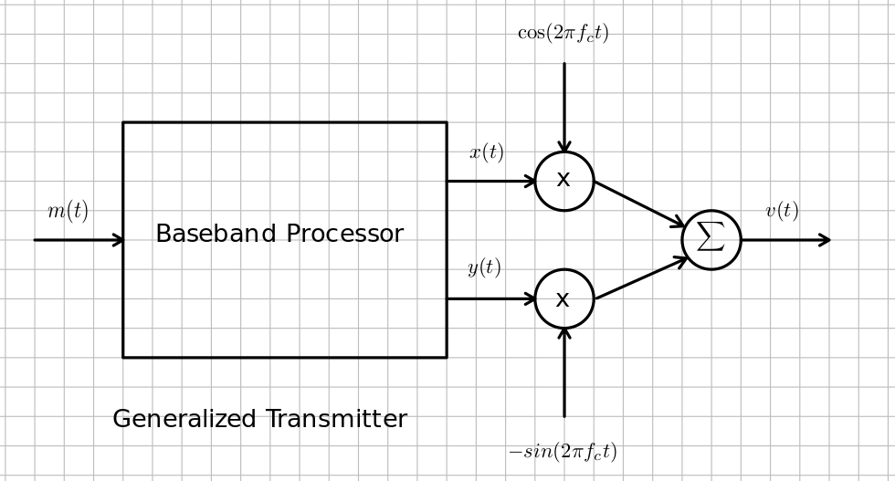 A generalized receiver can be made like this.
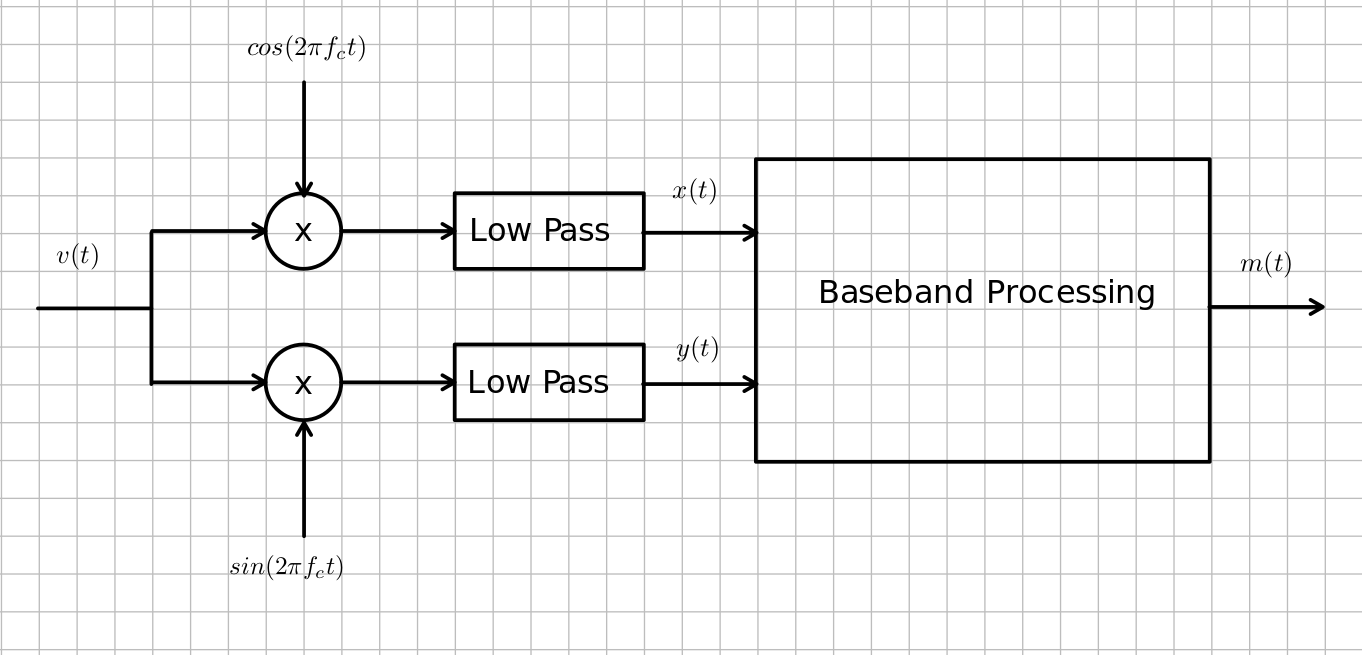 This is how most software defined radios work. A software defined radio allows you to demodulate any kind of modulation by only changing the software. It analog radios, you have to change the whole circuit topology, because analog circuits must be designed so that they do the mathematics in the baseband unit on the voltages in the circuit. Small parametric changes in the analog circuits required you to change the values of components, and rebuild the circuit with those new values. The software defined radio only needs numbers in data to be changed which is so easy in comparison.
- Find the impulse response response for the filter whose transfer function is $-jsgn(f)$. You will need to use the fact that you expect the inverse transform to be a real odd function of time, and that $$\mathscr {F^{-1}}\left[\frac{dX}{df}\right] = j2\pi t x(t)$$ while noting that: $$\frac {d}{df} sgn(f) = 2\delta(f)$$ This operation of this filter is known as a Hilbert transform. It changes every $cos(2\pi f t)$ into a $sin(2\pi f_c t)$, or makes a $90 ^{\circ}$ phase shift on every frequency component.
- Draw a block diagram for a single sideband transmitter.
- Draw a block diagram for a single sideband receiver.
- Show how and what block to change to make the above block diagrams work as a double sideband transmitter and receiver?