An Ideal Transformer Example: Difference between revisions
Jump to navigation
Jump to search
No edit summary |
|||
| Line 26: | Line 26: | ||
Since <math>{i_{1}}=\frac{e_{1}}{R_{th}}</math>, |
Since <math>{i_{1}}=\frac{e_{1}}{R_{th}}</math>, |
||
<math>{i_{1}}=\frac{120\sqrt{2}}{45+j27}</math> |
<math>{i_{1}}=\frac{120\sqrt{2}}{45+j27} A</math> |
||
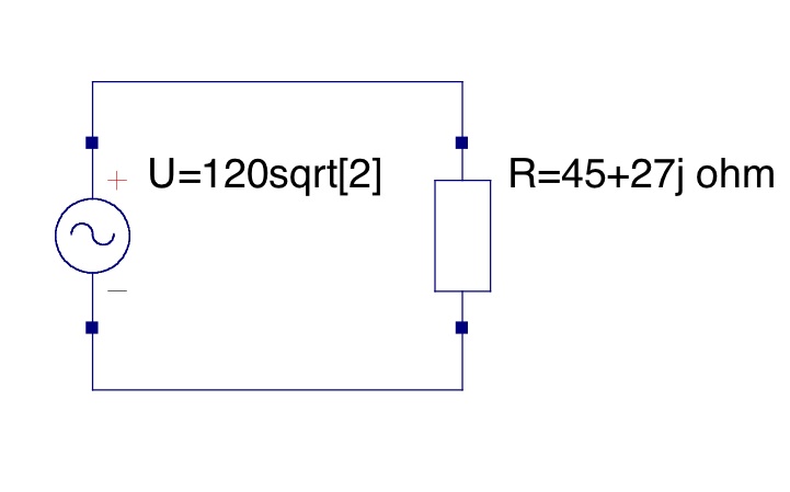
Since this is an ideal transformer, it can be modeled by this simple circuit: |
Since this is an ideal transformer, it can be modeled by this simple circuit: |
||
Revision as of 00:42, 19 January 2010
Consider a simple, transformer with two windings. Find the current provided by the voltage source.
- Winding 1 has a sinusoidal voltage of ° applied to it at a frequency of 60Hz.
- The combined load on winding 2 is
Solution
, so
Therefore,
Now the Thevenin equivalent impedance, , is found through the following steps:
Now, substituting:
Since ,
Since this is an ideal transformer, it can be modeled by this simple circuit:

Contributors
Read By
John Hawkins


