FIR Filters: Difference between revisions
Jump to navigation
Jump to search
No edit summary |
mNo edit summary |
||
| Line 2: | Line 2: | ||
[[Image:firtap.jpg]] |
[[Image:firtap.jpg]] |
||
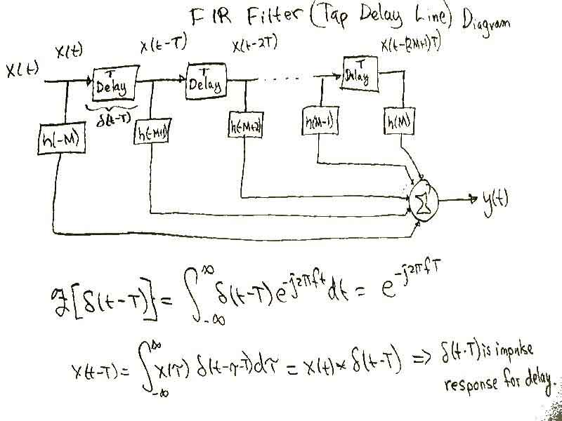
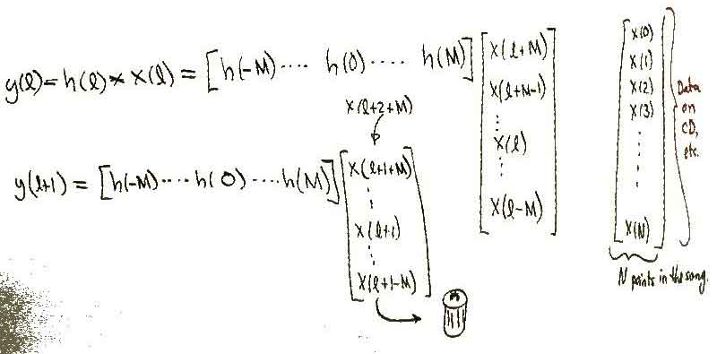
Above is shown the Tap Delay Line version of an FIR filter. It can actually be created in an analog circuit using transmission lines for the T Delay, resistors, an opamp, and an inverting summer to sum them all together. In the digital sense whats really happening here is that the output of the FIR filter (y(l)) is the convolution of h(l) with x(l) as shown below. |
|||
The output of an FIR filter (y(l)) is the convolution of h(l) with x(l). It can simply be viewed as a multiply and accumulate. |
|||
[[Image:firgarbage.jpg]] |
[[Image:firgarbage.jpg]] |
||
It can simply be viewed as a multiply and accumulate becuase we are simply |
|||
Revision as of 05:14, 10 December 2004
Finite Impulse Response Filters
Above is shown the Tap Delay Line version of an FIR filter. It can actually be created in an analog circuit using transmission lines for the T Delay, resistors, an opamp, and an inverting summer to sum them all together. In the digital sense whats really happening here is that the output of the FIR filter (y(l)) is the convolution of h(l) with x(l) as shown below.
It can simply be viewed as a multiply and accumulate becuase we are simply

