Intro to CAD: Difference between revisions
| Line 81: | Line 81: | ||
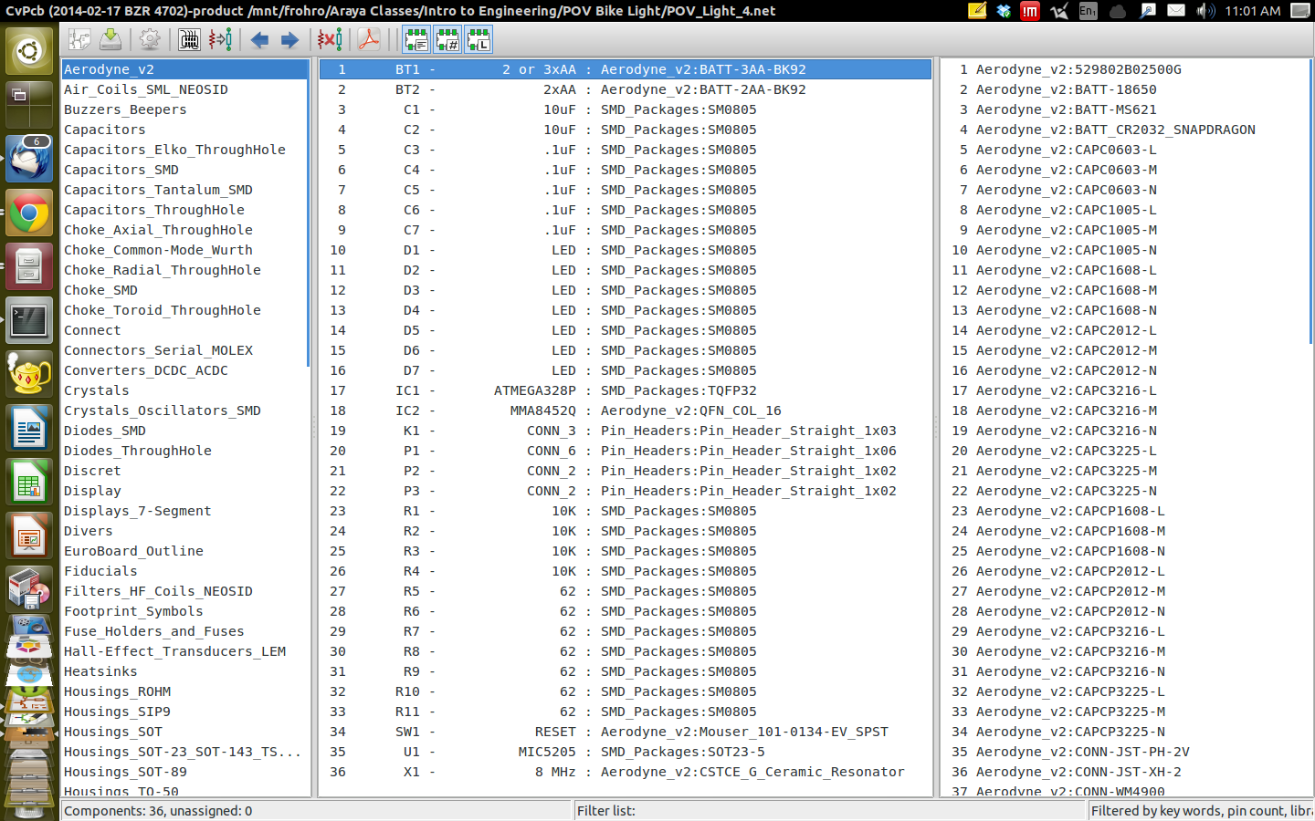
* Make sure to point the library tables to your [http://people.wallawalla.edu/~Rob.Frohne/ClassHandouts/Intro_to_Cad/Aerodyne_v2.pretty.tar.gz Aerodyne_v2.pretty] directory, and select the library type as kicad. You find the tables in CVPCB under Preferences->Library Tables, and you can add a line in the project specific tables. The ${KIPRJMOD} environment variable expansion is the directory of your project. [[File:Project_Tables.png|1024px|thumb|left|Project Files Screenshot]] |
* Make sure to point the library tables to your [http://people.wallawalla.edu/~Rob.Frohne/ClassHandouts/Intro_to_Cad/Aerodyne_v2.pretty.tar.gz Aerodyne_v2.pretty] directory, and select the library type as kicad. You find the tables in CVPCB under Preferences->Library Tables, and you can add a line in the project specific tables. The ${KIPRJMOD} environment variable expansion is the directory of your project. [[File:Project_Tables.png|1024px|thumb|left|Project Files Screenshot]] |
||
* Now you should be able to find the parts you need to associate in PCBNew. |
* Now you should be able to find the parts you need to associate in PCBNew. |
||
====PCBNew, Designing your Circuit Board==== |
|||
* After saving in CVPCB, go back to EESchema and start PCBNew. |
|||
* Load the [http://people.wallawalla.edu/~Rob.Frohne/ClassHandouts/Intro_to_Cad/intro_batterybrd.dxf board outline] using File->Import->DXF File. |
|||
* Position it in the middle. |
|||
* Read the netlist and make sure you have no errors in the messages. |
|||
* Place the parts, being sure to place the bypass capacitors (10uF and 0.1uF from power to ground) near the IC they are associated with. Be careful to put the parts on the side of the board you want them to be on, batteries on one side and components on the other, so the assembly will nicely fit into the plastic tubes we have ordered. Try and minimize the crossing in the rats nest by placement and orientation of the parts. Be sure your LEDs are organized and evenly spaced so they will shine where you want them. Don't space the ICs out too much, but leave a little room for traces on your board. |
|||
* Set the Design Rules to 0.008 inches for clearance and track width in the Net Classes Editor, and the minimum track width in the Global Design Rules. |
|||
====PCBNew, Designing your Circuit Board==== |
====PCBNew, Designing your Circuit Board==== |
||
* After saving in PCBNew, go back to EESchema and start PCBNew. |
* After saving in PCBNew, go back to EESchema and start PCBNew. |
||
Revision as of 08:01, 19 February 2014
This page is for the Intro to Engineering ENGR 122 EE/CPE Section
Two Dimensional CAD
- DraftSight is an AutoCAD clone. Presently it is rather like AutoCAD 2006 or 2007.
- Orthographic Projection (Front, Side and Top View) Drawing Tutorial
Persistence of Vision Bike Light Project
This project will use a 3.3 volt Arduino Pro Mini clone that you will design the circuit board, housing, and software for. Persistence of vision is a psychological effect that allows you to see two dimensional images that were created by one dimensional flashing LEDs. Here are some similar projects:
- This is video shows some POV projects from Japan.
- Arduino on a breadboard spinning with a motor.
- Another spinning POV display.
- Simple Code for a simple POV device using the Arduino.
- Another simple Arduino POV device with understandable code.
- A POV wand with 20 LEDs, and fairly understandable code.
We will have an MMA8452 accelerometer that communicates via a serial I2C interface. The accelerometer will measure the angular acceleration, which will allow the velocity of the bike wheel to be calculated. This will make it possible to flash LEDs at the proper time intervals to spell words, draw pictures, etc., as you ride your bike down the road at night.
The power source for your POV device can be two or three AA, or AAA batteries. You need to design the packaging. Some suggestions that you can consider are:
- Use clear vinyl tubing and corks in the end to house the circuit board, and tie wrap it to the spokes on your bike.
- The LEDs we purchased are 20 mA with a forward voltage drop of 2.3 volts, and there are some restrictions on the currents you can draw from the ATMEGA328P shown here.
- Schematic of the accelerometer from Sparkfun
- Schematic of the Arduino we are basing this from
Kicad Libraries
- MMA8452Q Accelerometer EESchema library
- MIC5205 Voltage Regulator EESchema library
- Battery EESchema library
Footprints for CVPCB and PCBNew
- Use the BAT-AA-BK92 footprint
- This is a document telling about the QFN footprints.
- This library (Aerodyne_v2.pretty) has all the special footprints we need.
- This is the board outline drawing. You can import this into PCBNew, using File->Import->DXF File.
EESchema Checklist
- ATMEGA328P
- MMA8452Q
- MIC5205
- Do you really want an LED to tell you the device is on? (I'm guessing probably not, so make sure you didn't put one in if you don't.)
- Batteries
- Programming cable connector
- LEDs
- Are the LEDs distributed over Ports B, C and D?
- No errors in the design check?
- Do you have the DOC linked to the datasheet for each important part?
- Do you have the datasheet URL in the datasheet field for each important part?
- Does your schematic look need and tidy?
- Do you have pull up resistors on the I2C bus lines SCL, SDA, and SA0?
Example Schematics & Footprints
- This is an example schematic. It has provision using jumpers K1 and P3 to select either two or three batteries and a voltage regulator, or two batteries without a regulator. You don't need to do this. I am doing it, so I can have a board that can be configured either way for debugging possible issues. I recommend picking one or the other power supply method.
- Example Footprint Selection You need to select the Aerodyne_v2.pretty in the Preferences->Library Tables in CVPCB in order to find the special footprints.
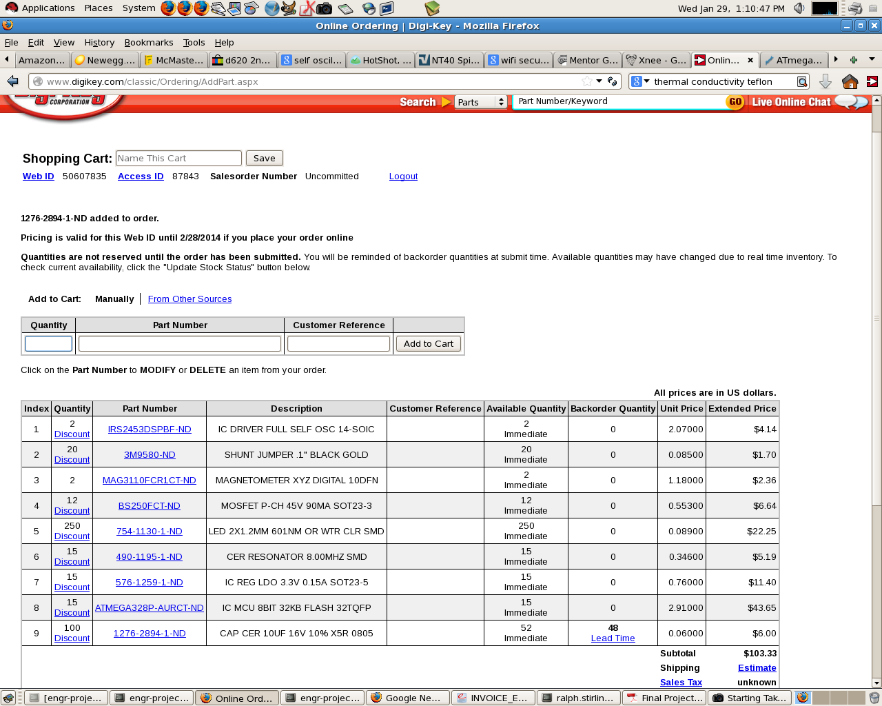
Parts Ordered By Ralph
Kicad Videos and Other Information
Getting Started with Kicad
Setting Up the Environment and Getting Started
- Some environment variables should be set such as the two below. Put them in your ~/.profile file at the end.
export KIGITHUB='https://github.com/KiCAD'
export KISYS3DMOD='/usr/local/share/kicad/modules/packages3d'
- In order for them to be activated, you need to logout and login again, or if you don't want to do than right now you can also paste the two lines above into a terminal and start kicad from that.
- Some environment variables should be set such as the two below. Put them in your ~/.profile file at the end.
export KIGITHUB='https://github.com/KiCAD'
export KISYS3DMOD='/usr/local/share/kicad/modules/packages3d'
kicad
- If you want the 3D viewer to know about your Aerodyne_v2 parts, you need to put a symbolic link to the 3D parts in the /usr/local/share/kicad/modules/packages3d/ directory, by doing this from the directory containing the KiCadLib-master directory.
$ sudo ln -s /KiCadLib-master/3D /usr/local/share/kicad/modules/packages3d/3D
Make the Schematic in EESchema
You should have done this already.
CVPCB, Associating Footprint Patterns with Parts
- Start CVPCB from EESchema after completing the design rules check and creating a netlist.
- Make sure to point the library tables to your Aerodyne_v2.pretty directory, and select the library type as kicad. You find the tables in CVPCB under Preferences->Library Tables, and you can add a line in the project specific tables. The ${KIPRJMOD} environment variable expansion is the directory of your project.
- Now you should be able to find the parts you need to associate in PCBNew.

PCBNew, Designing your Circuit Board
- After saving in CVPCB, go back to EESchema and start PCBNew.
- Load the board outline using File->Import->DXF File.
- Position it in the middle.
- Read the netlist and make sure you have no errors in the messages.
- Place the parts, being sure to place the bypass capacitors (10uF and 0.1uF from power to ground) near the IC they are associated with. Be careful to put the parts on the side of the board you want them to be on, batteries on one side and components on the other, so the assembly will nicely fit into the plastic tubes we have ordered. Try and minimize the crossing in the rats nest by placement and orientation of the parts. Be sure your LEDs are organized and evenly spaced so they will shine where you want them. Don't space the ICs out too much, but leave a little room for traces on your board.
- Set the Design Rules to 0.008 inches for clearance and track width in the Net Classes Editor, and the minimum track width in the Global Design Rules.
PCBNew, Designing your Circuit Board
- After saving in PCBNew, go back to EESchema and start PCBNew.
- Import your