Intro to CAD: Difference between revisions
No edit summary |
|||
| Line 105: | Line 105: | ||
Here is a video showing how to setup the Arduino IDE for your Pro Mini 3.3V ATMEGA328P device. |
Here is a video showing how to setup the Arduino IDE for your Pro Mini 3.3V ATMEGA328P device. |
||
{{#ev:youtube|BCtseJ3Jov8}} |
|||
====Programming Hardware Connections==== |
====Programming Hardware Connections==== |
||
The Pro Mini requires a USB to serial TTL device to program it. The ones we purchased don't have the DTR line, so you have to push the reset button on the arduino, then hit the upload button on your computer and then release the reset button on the arduino. The [[File:Arduino-serial.jpg]] serial connections are shown in the photo. The color code for the wires is: |
The Pro Mini requires a USB to serial TTL device to program it. The ones we purchased don't have the DTR line, so you have to push the reset button on the arduino, then hit the upload button on your computer and then release the reset button on the arduino. The [[File:Arduino-serial.jpg]] serial connections are shown in the photo. The color code for the wires is: |
||
Revision as of 12:39, 23 February 2014
This page is for the Intro to Engineering ENGR 122 EE/CPE Section
Two Dimensional CAD
- DraftSight is an AutoCAD clone. Presently it is rather like AutoCAD 2006 or 2007.
- Orthographic Projection (Front, Side and Top View) Drawing Tutorial
Persistence of Vision Bike Light Project
This project will use a 3.3 volt Arduino Pro Mini clone that you will design the circuit board, housing, and software for. Persistence of vision is a psychological effect that allows you to see two dimensional images that were created by one dimensional flashing LEDs. Here are some similar projects:
- This is video shows some POV projects from Japan.
- Arduino on a breadboard spinning with a motor.
- Another spinning POV display.
- Simple Code for a simple POV device using the Arduino.
- Another simple Arduino POV device with understandable code.
- A POV wand with 20 LEDs, and fairly understandable code.
We will have an MMA8452 accelerometer that communicates via a serial I2C interface. The accelerometer will measure the angular acceleration, which will allow the velocity of the bike wheel to be calculated. This will make it possible to flash LEDs at the proper time intervals to spell words, draw pictures, etc., as you ride your bike down the road at night.
The power source for your POV device can be two or three AA, or AAA batteries. You need to design the packaging. Some suggestions that you can consider are:
- Use clear vinyl tubing and corks in the end to house the circuit board, and tie wrap it to the spokes on your bike.
- The LEDs we purchased are 20 mA with a forward voltage drop of 2.3 volts, and there are some restrictions on the currents you can draw from the ATMEGA328P shown here.
- Schematic of the accelerometer from Sparkfun
- Schematic of the Arduino we are basing this from
Kicad Libraries
- MMA8452Q Accelerometer EESchema library
- MIC5205 Voltage Regulator EESchema library
- Battery EESchema library
Footprints for CVPCB and PCBNew
- Use the BAT-AA-BK92 footprint
- This is a document telling about the QFN footprints.
- This library (Aerodyne_v2.pretty) has all the special footprints we need.
- This is the board outline drawing. You can import this into PCBNew, using File->Import->DXF File.
EESchema Checklist
- ATMEGA328P
- MMA8452Q
- MIC5205
- Do you really want an LED to tell you the device is on? (I'm guessing probably not, so make sure you didn't put one in if you don't.)
- Batteries
- Programming cable connector
- LEDs
- Are the LEDs distributed over Ports B, C and D?
- No errors in the design check?
- Do you have the DOC linked to the datasheet for each important part?
- Do you have the datasheet URL in the datasheet field for each important part?
- Does your schematic look need and tidy?
- Do you have pull up resistors on the I2C bus lines SCL, SDA, and SA0?
Example Schematics & Footprints
- This is an example schematic. It has provision using jumpers K1 and P3 to select either two or three batteries and a voltage regulator, or two batteries without a regulator. You don't need to do this. I am doing it, so I can have a board that can be configured either way for debugging possible issues. I recommend picking one or the other power supply method.
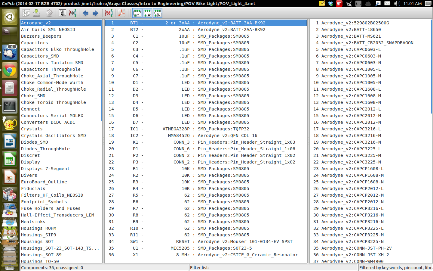
- Example Footprint Selection You need to select the Aerodyne_v2.pretty in the Preferences->Library Tables in CVPCB in order to find the special footprints.
Parts Ordered By Ralph
Kicad Videos and Other Information
Getting Started with Kicad
Setting Up the Environment and Getting Started
- Some environment variables should be set such as the two below. Put them in your ~/.profile file at the end.
export KIGITHUB='https://github.com/KiCAD'
export KISYS3DMOD='/usr/local/share/kicad/modules/packages3d'
- In order for them to be activated, you need to logout and login again, or if you don't want to do than right now you can also paste the two lines above into a terminal and start kicad from that.
- Some environment variables should be set such as the two below. Put them in your ~/.profile file at the end.
export KIGITHUB='https://github.com/KiCAD'
export KISYS3DMOD='/usr/local/share/kicad/modules/packages3d'
kicad
- If you want the 3D viewer to know about your Aerodyne_v2 parts, you need to put a symbolic link to the 3D parts in the /usr/local/share/kicad/modules/packages3d/ directory, by doing this from the directory containing the KiCadLib-master directory.
$ sudo ln -s /KiCadLib-master/3D /usr/local/share/kicad/modules/packages3d/3D
Make the Schematic in EESchema
You should have done this already.
CVPCB, Associating Footprint Patterns with Parts
- Start CVPCB from EESchema after completing the design rules check and creating a netlist.
- Make sure to point the library tables to your Aerodyne_v2.pretty directory, and select the library type as kicad. You find the tables in CVPCB under Preferences->Library Tables, and you can add a line in the project specific tables. The ${KIPRJMOD} environment variable expansion is the directory of your project.

- Now you should be able to find the parts you need to associate in PCBNew.
PCBNew, Designing your Circuit Board
- After saving in PCBNew, go back to EESchema and start PCBNew.
- Import your board outline using File->Import->DXF File, and place it in the middle.
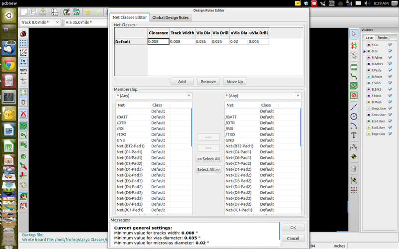
- In the Design Rules, change the clearance and track width to 0.008 inches under Net Classes Editor, and set the minimum trace width to 0.008 inches in the Global Design Rules.
- Using the tool on the right of the toolbar for fast access to the web based router, export your Spectra Design file and open it in the web based Free Router. This may take a minute.
- In the Free Router, under Parameter->Autoroute click the Detail Parameter, and set the via costs to 8. Hit return and close the windows for parameters.
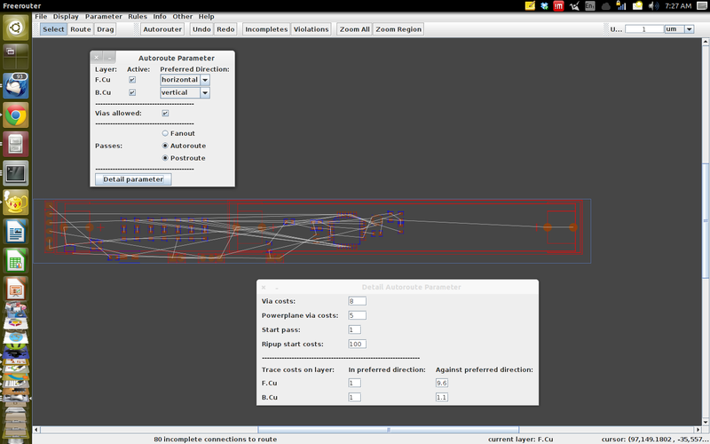
- Hit the autorouter button and watch it route your board.
- You may have some violations because the pitch of the accelerometer is smaller than we have allowed somewhere. You can ignore this.
- Make sure everything went well and your board was able to complete routing.
- Save the Spectra Session .ses file, and import it back into PCBNew.
- Run a Design Rules Check in PCBNew, and fix any problems.
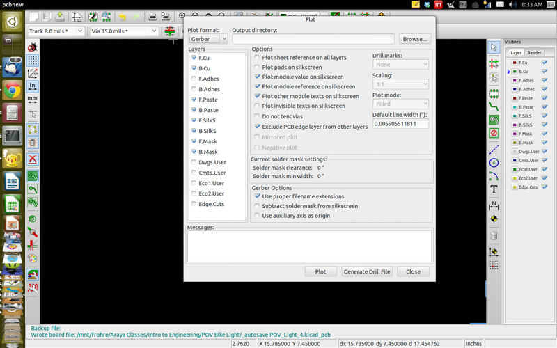
- Plot the Gerbers, being sure to check the boxes for all the ones we need.
- Compress your directory, and upload it to D2L.


Arduino Programming
This section describes how to program your Arduino. We will start out with your Pro Mini.
Tool Chain Setup
You can program Arduinos from a PC, Mac or Linux. On OS X and Windows, you need to download the software:
- The download page is here.
- On Ubuntu you can load it with Synaptic Package Manager (synaptic), and it should already be there on the virtual machines we set up.
Here is a video showing how to setup the Arduino IDE for your Pro Mini 3.3V ATMEGA328P device.
Programming Hardware Connections
The Pro Mini requires a USB to serial TTL device to program it. The ones we purchased don't have the DTR line, so you have to push the reset button on the arduino, then hit the upload button on your computer and then release the reset button on the arduino. The  serial connections are shown in the photo. The color code for the wires is:
- Black is GND which connects to the arduino GND.
- Red is +5 volts which connects to the arduino VCC.
- Green is TXO which connects to the arduino RXI
- White is RXI which connects to the arduino TXO
Note: The serial communications protocol is kind of like whispering secrets. You put your lips up to the other person's ear. (TXO -> RXI) T stands for transmit, and R for receive.