Chapter 4: Difference between revisions
Jump to navigation
Jump to search
No edit summary |
|||
| Line 10: | Line 10: | ||
{| class="wikitable" border="1" style="text-align:center;" |
{| class="wikitable" border="1" style="text-align:center;" |
||
|+ |
|+ |
||
! Base-Emitter !! Collector-Base!! Region |
! Base-Emitter !! Collector-Base!! Region |
||
|- |
|- |
||
| FB|| FB || Saturation |
| FB|| FB || Saturation |
||
|- |
|- |
||
| FB|| RB || Active |
| FB|| RB || Active |
||
|- |
|- |
||
| RB || FB || Reverse Active |
| RB || FB || Reverse Active |
||
Revision as of 11:00, 3 March 2010
Bipolar Junction Transistor
- NPN: Not Pointing iN
- PNP: Pointing iN Please
- The arrow is for the emitter current. For an NPN the current flows into the collector. For a PNP the current flows out of the collector.
How a BJT works
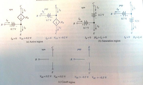
Large-Signal DC models
| Base-Emitter | Collector-Base | Region |
|---|---|---|
| FB | FB | Saturation |
| FB | RB | Active |
| RB | FB | Reverse Active |
| RB | RB | Cutoff |
| Region | NPN | PNP |
|---|---|---|
| Saturation | and | and |
| Active | and | and |
| Cutoff | and | and |
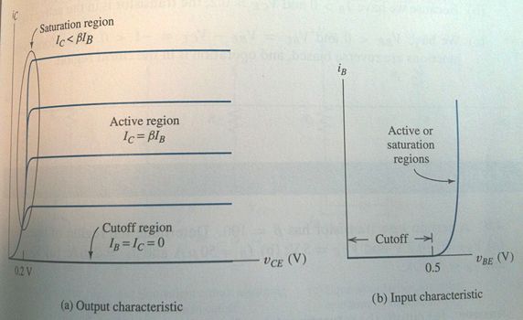
- Active: The normal mode of operation. This mode has the largest common-emitter current gain.
- Reverse Active: The collector and emitter roles are reversed. Most BJTs are not symmetrical, thus and take on different values.
- Saturation:
- Cutoff:
- What are the Saturation, Reverse Active and Cutoff regions used for?
- Why do we always seem to use a common emitter configuration?
- What does the Reverse Active large-signal model look like? How about graphically?
- What is the Triode region?
- For the Saturation region, why is 0.2V the magic number for V_CE?


