Chapter 4: Difference between revisions
Jump to navigation
Jump to search
| Line 50: | Line 50: | ||
| [[Image:IMG_0287.jpg|x350px|none]] |
| [[Image:IMG_0287.jpg|x350px|none]] |
||
|} |
|} |
||
===Bias-Circuit Design=== |
|||
*Fixed-base bias circuit is a very simplistic method that does not deal well with a wide variety of <math>/beta</math> values. |
|||
* |
|||
===Questions=== |
===Questions=== |
||
Revision as of 14:42, 3 March 2010
Bipolar Junction Transistor
- NPN: Not Pointing iN
- PNP: Pointing iN Please
- The arrow is for the emitter current.
- For an NPN the current flows into the collector. For a PNP the current flows out of the collector.
How a BJT works
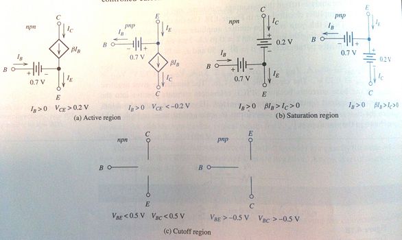
Large-Signal DC models
|
|
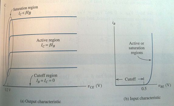
- Active: The normal mode of operation. This mode has the largest common-emitter current gain.
- Reverse Active: The collector and emitter roles are reversed. Most BJTs are not symmetrical, thus and take on different values.
- Saturation: High current from the emitter to collector. Logical "on".
- Cutoff: Very little current flow. Logical "off".
Large-Signal DC Analysis
- Assume an operating region for the BJT.
- Solve the circuit to find
- Check the values to see if they match the region constraints.
Bias-Circuit Design
- Fixed-base bias circuit is a very simplistic method that does not deal well with a wide variety of values.
Questions
- Why do we always seem to use a common emitter configuration? Common-base and common-collector have different properties.
- Daisy chaining the voltage doubler? Go up?
- For P3.17 make the glob of sauder assuming they're all on and check the currents running through each one. Make sure they go the right way, and add up?
- How do we get around the problem of the fixed-base bias current? Looks like you can fix it with two voltage sources, but is there a better method?


