Matlab or Octave Script for this problem.: Difference between revisions
Jump to navigation
Jump to search
New page: % This octave/Matlab script demonstrates the state space model of the J=0.01; b=0.1; K=0.01; R=1; L=0.5; A1=[[0,1,0];[0,-b/J,K/J];[0,-K/L,-R/L]]; B1=[0,0,1/L]'; C1=[0,1,0]; % The outp... |
No edit summary |
||
| (7 intermediate revisions by the same user not shown) | |||
| Line 1: | Line 1: | ||
% This octave/Matlab script demonstrates the state space model of the | % This octave/Matlab script demonstrates the state space model of the | ||
J=0.01; | J=0.01; | ||
b=0.1; | b=0.1; | ||
K=0.01; | K=0.01; | ||
R=1; | R=1; | ||
L=0.5; | L=0.5; | ||
A1=[[0,1,0];[0,-b/J,K/J];[0,-K/L,-R/L]]; | A1=[[0,1,0];[0,-b/J,K/J];[0,-K/L,-R/L]]; | ||
B1=[0,0,1/L]'; | B1=[0,0,1/L]'; | ||
C1=[0,1,0]; % The output is the angular velocity omega. | C1=[0,1,0]; % The output is the angular velocity omega. | ||
sys1=ss(A1,B1,C1); % Note that theta cannot be controlled. | sys1=ss(A1,B1,C1); % Note that theta cannot be controlled. | ||
% So we use only the theta dot, and i_a as state variables. | % There is a warning in octave from this. | ||
A2=[[-b/J, K/J];[-K/L,-R/L]]; | % So we use only the theta dot, and i_a as state variables. | ||
B2=[0,1/L]'; | A2=[[-b/J, K/J];[-K/L,-R/L]]; | ||
C2=[1,0]; | B2=[0,1/L]'; | ||
sys2=ss(A2,B2,C2); | C2=[1,0]; | ||
figure(1) | sys2=ss(A2,B2,C2); | ||
clf; | figure(1) | ||
clf; | |||
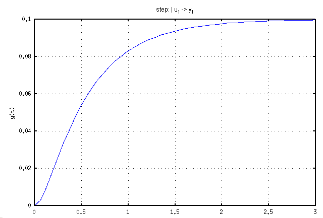
Here is the unit step response for <math>\omega</math> or angular velocity as a function of time. | |||
[[Image:Step_response_dc_motor.png]] | |||
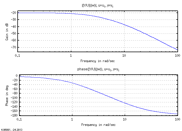
Here is the system response with the output being <math>\omega</math> and the input being the input voltage. | |||
[[Image:Bode_Plot_DC_Motor.png]] | |||
Latest revision as of 11:50, 10 March 2010
% This octave/Matlab script demonstrates the state space model of the
J=0.01;
b=0.1;
K=0.01;
R=1;
L=0.5;
A1=[[0,1,0];[0,-b/J,K/J];[0,-K/L,-R/L]];
B1=[0,0,1/L]';
C1=[0,1,0]; % The output is the angular velocity omega.
sys1=ss(A1,B1,C1);  % Note that theta cannot be controlled.
% There is a warning in octave from this.
% So we use only the theta dot, and i_a as state variables.
A2=[[-b/J, K/J];[-K/L,-R/L]];
B2=[0,1/L]';
C2=[1,0];
sys2=ss(A2,B2,C2);
figure(1)
clf;
Here is the unit step response for or angular velocity as a function of time.
Here is the system response with the output being and the input being the input voltage.

