'Exact' Transformer Model: Difference between revisions
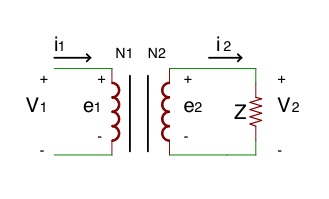
Luke.chilson (talk | contribs) New page: == Ideal Transformers == To start off lets review the ideal transformer model with this illustration. thumb|widthpx| |
Luke.chilson (talk | contribs) No edit summary |
||
| (One intermediate revision by the same user not shown) | |||
| Line 1: | Line 1: | ||
== Ideal Transformer == | |||
To start off lets review the Ideal Transformer model with this illustration. | |||
[[Image:Ideal Transformer.jpg ]] | |||
== | From this and using the fact that in an Ideal Transformer power input is equal to power output we are able to derive a very useful set of identities. Namely: | ||
[[Image: | |||
<math> | |||
V1 / V2 = N1 / N2 = I2 / I1 | |||
</math> | |||
== Exact Transfromer == | |||
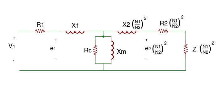
Now this model does not take into account several things such as resistance in the windings and losses in the core. If we add these in where: | |||
R1 = Winding resistance on the primary side | |||
X1 = Leakage inductance on the primary side | |||
Rc = The real portion of the core losses | |||
Xm = Is used to maintain mutual flux in the core | |||
R2 = Winding resistance on the secondary side | |||
X2 = Leakage inductance on the secondary side | |||
We are left with what is often referred to as the Exact Transformer model, illustrated below. | |||
[[Image:Exact_transformer.jpg ]] | |||
== Lumped Circuit Transformer Model == | |||
Using what we know about an ideal transformer, we are able to apply a transformation (multiplication by an Impedance Scaling Factor) to the impedance located on the secondary side effectively moving them to the primary side. This will allow us take out the Ideal Transformer from the exact model and leave us with a Lumped Circuit model. | |||
[[Image:Lumpedtransformer.jpg]] | |||
Latest revision as of 08:50, 17 March 2010
Ideal Transformer
To start off lets review the Ideal Transformer model with this illustration.

From this and using the fact that in an Ideal Transformer power input is equal to power output we are able to derive a very useful set of identities. Namely:
Exact Transfromer
Now this model does not take into account several things such as resistance in the windings and losses in the core. If we add these in where:
R1 = Winding resistance on the primary side X1 = Leakage inductance on the primary side
Rc = The real portion of the core losses Xm = Is used to maintain mutual flux in the core
R2 = Winding resistance on the secondary side X2 = Leakage inductance on the secondary side
We are left with what is often referred to as the Exact Transformer model, illustrated below.

Lumped Circuit Transformer Model
Using what we know about an ideal transformer, we are able to apply a transformation (multiplication by an Impedance Scaling Factor) to the impedance located on the secondary side effectively moving them to the primary side. This will allow us take out the Ideal Transformer from the exact model and leave us with a Lumped Circuit model.
