Christman GeneralizedReceiver: Difference between revisions
No edit summary |
No edit summary |
||
| Line 8: | Line 8: | ||
<br/> |
<br/> |
||
<center> |
<center> |
||
| ⚫ | |||
| ⚫ | |||
<br/> |
|||
| ⚫ | |||
where <math>g(t) = x(t) + jy(t)</math> is the signal to be sent and <math>\scriptstyle e^{j\omega_{c}t} = \cos{\omega_{c}t} + j\sin{\omega_{c}t}</math> (Euler's identity) shifts the signal in the frequency domain by <math>\omega_{c} = 2 \pi f_{c}</math>. |
|||
| ⚫ | |||
<br/> |
<br/> |
||
The above formula can then be rewritten to obtain the following relationship: |
|||
<br/> |
<br/> |
||
<center> |
<center> |
||
<math>\displaystyle v(t) = Re[ |
<math>\displaystyle v(t) = Re[g(t) \cdot e^{j\omega_{c}t}] = Re[(x(t) + jy(t)) \cdot (\cos{\omega_{c}t} + j\sin{\omega_{c}t}) = x(t)\cos{\omega_{c}t} - y(t)\sin{\omega_{c}t}</math>. |
||
</center> |
</center> |
||
To visualize this process, observe the following figure: |
|||
<br/> |
<br/> |
||
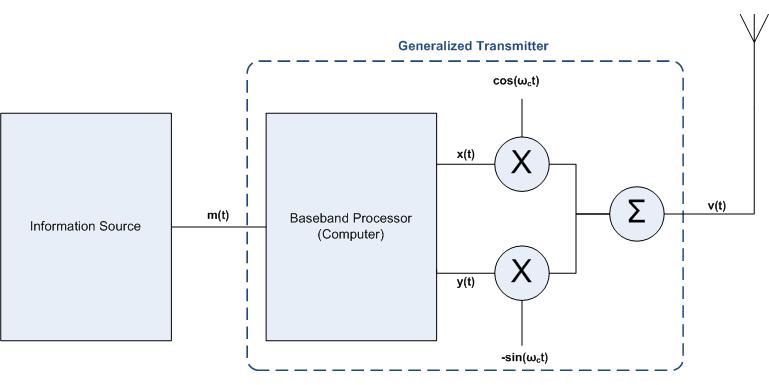
This is why it is necessary to split <math>m(t)</math> into the the two signals <math>x(t) \text{ and } y(t)</math>. As you can also from the above relationship, in order to obtain the appropriate output signal <math>v(t)</math> one must multiply <math>x(t)</math> by a cosine function and <math>y(t)</math> by a negative sine function and then sum the results (this is illustrated in the figure above). In simplified terms and details, this is essentially how the data <math>m(t)</math> is transmitted. The process of receiving the data is very similar, as is described below. |
This is why it is necessary to split <math>m(t)</math> into the the two signals <math>x(t) \text{ and } y(t)</math>. As you can also from the above relationship, in order to obtain the appropriate output signal <math>v(t)</math> one must multiply <math>x(t)</math> by a cosine function and <math>y(t)</math> by a negative sine function and then sum the results (this is illustrated in the figure above). In simplified terms and details, this is essentially how the data <math>m(t)</math> is transmitted. The process of receiving the data is very similar, as is described below. |
||
<br/> |
<br/> |
||
Revision as of 08:10, 6 April 2010
How It Works: Generalized Receiver
The process of transmitting data, , via a wireless signal, , is shown below:

As can be seen from the figure above, in order to transmit , one must first process the data using a baseband processor (usually accomplished with software). As a result of this process the original data will be split into two signals, and . Why is this you ask? In the world of "Communication Systems" a signal to be transmitted can be written as
,
where is the signal to be sent and (Euler's identity) shifts the signal in the frequency domain by .
The above formula can then be rewritten to obtain the following relationship:
.
To visualize this process, observe the following figure:
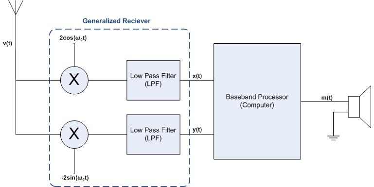
This is why it is necessary to split into the the two signals . As you can also from the above relationship, in order to obtain the appropriate output signal one must multiply by a cosine function and by a negative sine function and then sum the results (this is illustrated in the figure above). In simplified terms and details, this is essentially how the data is transmitted. The process of receiving the data is very similar, as is described below.


![{\displaystyle \displaystyle v(t)=Re[g(t)\cdot e^{j\omega _{c}t}]}](https://wikimedia.org/api/rest_v1/media/math/render/svg/84980ddc31ef70ba28686486029d15efd306809d)


![{\displaystyle \displaystyle v(t)=Re[g(t)\cdot e^{j\omega _{c}t}]=Re[(x(t)+jy(t))\cdot (\cos {\omega _{c}t}+j\sin {\omega _{c}t})=x(t)\cos {\omega _{c}t}-y(t)\sin {\omega _{c}t}}](https://wikimedia.org/api/rest_v1/media/math/render/svg/23ed92e222b39e76a528ba824c1867ab5e3175d9)
