Yet another Generalized Receiver Explanation: Difference between revisions
(New page: The very exciting radio project you have recently embarked on has many obstacles to overcome, but not understanding what you are building will no longer be one. This will be thanks to my ...) |
No edit summary |
||
| Line 1: | Line 1: | ||
The very exciting radio project you have recently embarked on has many obstacles to overcome, but not understanding what you are building will no longer be one. This will be thanks to my awesome explanation. |
The very exciting radio project you have recently embarked on has many obstacles to overcome, but not understanding what you are building will no longer be one. This will be thanks to my awesome explanation. |
||
You will be receiving a signal passed over the airwaves at a certain frequency. Encoded at that frequency will be the beautiful voice of Sandy Patty (more likely the frazzled voice of a ham radio operator). In reality, though, all this is inaudible because how high the frequency is. The sound recording has been taken from base-band and separated into a real and non-real part. In-order for the computer to make any sense of the input signal (v(t)) we must return it to base-band, and for the base-band signal to make any sense we need both the real (x(t)) and non-real part (y(t)). It is up to you and your design to decode the signal and give it to the computer so it can play it back in all its audio glory. |
You will be receiving a signal passed over the airwaves at a certain frequency. Encoded at that frequency will be the beautiful voice of Sandy Patty (more likely the frazzled voice of a ham radio operator). In reality, though, all this is inaudible because how high the frequency is. The sound recording has been taken from base-band and separated into a real and non-real part. In-order for the computer to make any sense of the input signal (v(t)) we must return it to base-band, and for the base-band signal to make any sense we need both the real (x(t)cos(wt)) and non-real part (y(t)sin(wt)). It is up to you and your design to decode the signal and give it to the computer so it can play it back in all its audio glory. |
||
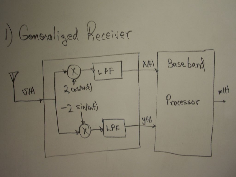
The block diagram for your design is probably: |
The block diagram for your design is probably: |
||
| Line 9: | Line 9: | ||
I know this because we have the same teacher. |
I know this because we have the same teacher. |
||
Once you have your signal received, it is split and passed through two different mixers and combined with two different waves (by a phase of pi/2). This may seem like it will only complicate things more but this is not the case |
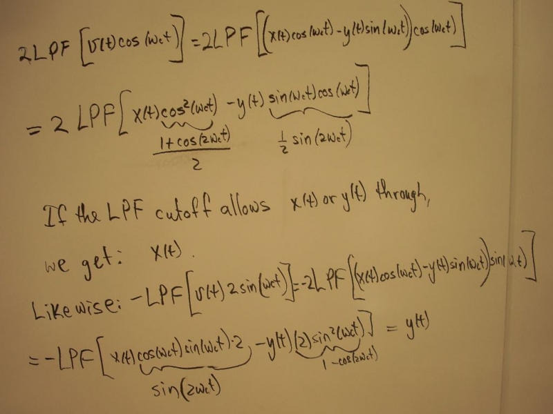
Once you have your signal received, it is split and passed through two different mixers and combined with two different waves (by a phase of pi/2). This may seem like it will only complicate things more but this is not the case. The frequency of the sine waves we use allows us to simplify the math and, physically, returns the frequency to base-band. Lets take a peak at some math: |
||
[[Image:Math.jpg]] |
[[Image:Math.jpg]] |
||
Revision as of 01:28, 8 April 2010
The very exciting radio project you have recently embarked on has many obstacles to overcome, but not understanding what you are building will no longer be one. This will be thanks to my awesome explanation.
You will be receiving a signal passed over the airwaves at a certain frequency. Encoded at that frequency will be the beautiful voice of Sandy Patty (more likely the frazzled voice of a ham radio operator). In reality, though, all this is inaudible because how high the frequency is. The sound recording has been taken from base-band and separated into a real and non-real part. In-order for the computer to make any sense of the input signal (v(t)) we must return it to base-band, and for the base-band signal to make any sense we need both the real (x(t)cos(wt)) and non-real part (y(t)sin(wt)). It is up to you and your design to decode the signal and give it to the computer so it can play it back in all its audio glory.
The block diagram for your design is probably:
I know this because we have the same teacher.
Once you have your signal received, it is split and passed through two different mixers and combined with two different waves (by a phase of pi/2). This may seem like it will only complicate things more but this is not the case. The frequency of the sine waves we use allows us to simplify the math and, physically, returns the frequency to base-band. Lets take a peak at some math:
(I am still not very good using the math tools in this editor)
Essential when you combine in the cosine with v(t)

