Matthew's Asgn: Difference between revisions
Jump to navigation
Jump to search
Btheredude (talk | contribs) No edit summary |
Btheredude (talk | contribs) No edit summary |
||
| Line 11: | Line 11: | ||
''I(0)=i'' |
''I(0)=i'' |
||
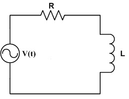
[[File:RLcircuit.jpg]] |
|||
The Laplace transform for an inductor |
|||
<math>\displaystyle\mathcal{L} \left\{f(t)\right\}</math> = <math>\ Ls + Li \,\!</math> |
|||
The Laplace transform for a resistor is just the resistor itself |
|||
<math>\displaystyle\mathcal{L} \left\{f(t)\right\}</math> = <math>\ R\,\!</math> |
|||
Therefore the Resulting Equation for the system after applying the Laplace Transform: |
|||
<math>\ 0 = -s/(s^2+w^2) + RI(s) + LsI(s) - Li \,\!</math> |
|||
Revision as of 16:06, 1 November 2010
I decided that I would attempt to perform a simple analysis of a series RL circuit, which could then be used to do a more complex analysis on a basic transformer. I have always had interest in electronics, and transformers are key to basic electronics.
I decided that i would do the analysis of a RL circuit with the variables instead of given values.
Given:
V(t)=
V(s)=
I(0)=i
The Laplace transform for an inductor
=
The Laplace transform for a resistor is just the resistor itself
=
Therefore the Resulting Equation for the system after applying the Laplace Transform:


