Engineering Electronics: Difference between revisions
Jump to navigation
Jump to search
| (78 intermediate revisions by the same user not shown) | |||
| Line 1: | Line 1: | ||
== | =Links= | ||
==ENGR 356 (Engineering Electronics I Class)== | |||
* [[What is Important, Voltage, Current or Power?]] | |||
* [http://fweb.wallawalla.edu/~frohro/ClassHandouts/Electronics/Exam%201%20356%20Review%20Sheet%202018.pdf Exam I ENGR 356 Tips] | |||
* Lab Write Up Documents | * Lab Write Up Documents | ||
**[http://www.edn.com/electronics-blogs/embedded-basics/4441329/10-Tips-On-Engineering-Notebooks?_mc=NL_EDN_EDT_EDN_today_20160203&cid=NL_EDN_EDT_EDN_today_20160203&elq=0b4fac0a65fb47b8976861525eebec99&elqCampaignId=26817&elqaid=30665&elqat=1&elqTrackId=6e60559ec79045ab97ce21a0687e9f74 Ten tips for your Engineering Notebook] | **[http://www.edn.com/electronics-blogs/embedded-basics/4441329/10-Tips-On-Engineering-Notebooks?_mc=NL_EDN_EDT_EDN_today_20160203&cid=NL_EDN_EDT_EDN_today_20160203&elq=0b4fac0a65fb47b8976861525eebec99&elqCampaignId=26817&elqaid=30665&elqat=1&elqTrackId=6e60559ec79045ab97ce21a0687e9f74 Ten tips for your Engineering Notebook] | ||
| Line 10: | Line 13: | ||
**[http://bitsavers.informatik.uni-stuttgart.de/pdf/wavetek/130_Aug72.pdf A really simple function generator,] but still a little more complicated than yours. However, you will notice the hysteresis oscillator is used in it too. | **[http://bitsavers.informatik.uni-stuttgart.de/pdf/wavetek/130_Aug72.pdf A really simple function generator,] but still a little more complicated than yours. However, you will notice the hysteresis oscillator is used in it too. | ||
*[http://ocw.mit.edu/ans7870/RES/RES.6-010/MITRES_6-010S13_comchaptrs.pdf Operational Amplifiers, Theory and Practice, by James Roberage] | *[http://ocw.mit.edu/ans7870/RES/RES.6-010/MITRES_6-010S13_comchaptrs.pdf Operational Amplifiers, Theory and Practice, by James Roberage] | ||
[http://users.ece.gatech.edu/mleach/ece3050/sp00/ce-ccamp.pdf Common Emitter/Common Collector Amplifier Example] | *[http://www-g.eng.cam.ac.uk/mmg/teaching/linearcircuits/ Semiconductor Animations] | ||
*[http://users.ece.gatech.edu/mleach/ece3050/sp00/ce-ccamp.pdf Common Emitter/Common Collector Amplifier Example] | |||
===LTSpice=== | |||
[http://ltspice.linear.com/software/LTspiceGettingStartedGuide.pdf LTSpice Getting Started Guide] | [http://ltspice.linear.com/software/LTspiceGettingStartedGuide.pdf LTSpice Getting Started Guide] | ||
[[Qucs Simulations]] | LTSpice is a good simulator and runs on Windows, Linux (under wine), and OS X. | ||
*[https://csserver.evansville.edu/~richardson/courses/Tutorials/audio/AudioProcessing.pdf How to connect LTSpice and Gnu Octave for Analysis] | |||
==ENGR 357 (Engineering Electronics II Class)== | |||
===[[Qucs Simulations]]=== | |||
*[http://www.ntia.doc.gov/osmhome/allochrt.pdf United States Frequency Allocations] | *[http://www.ntia.doc.gov/osmhome/allochrt.pdf United States Frequency Allocations] | ||
*[http://www.edn.com/design/analog/4402049/Temperature-and-voltage-variation-of-ceramic-capacitors--or-why-your-4-7--F-capacitor-becomes-a-0-33--F-capacitor?cid=EDNToday Ceramic Capacitors Change Value with Applied Voltage and Temperature (especially small surface mount ones)] | *[http://www.edn.com/design/analog/4402049/Temperature-and-voltage-variation-of-ceramic-capacitors--or-why-your-4-7--F-capacitor-becomes-a-0-33--F-capacitor?cid=EDNToday Ceramic Capacitors Change Value with Applied Voltage and Temperature (especially small surface mount ones)] | ||
*[http://www.ece.ucsb.edu/Faculty/rodwell/Classes/ece218b/ECE218b.htm#_Toc345504902 Steve Long's and Mark Rodwell's Communications Electronics Course.] See especially Steve Long's Notes at the end of the page. They are good. | *[http://www.ece.ucsb.edu/Faculty/rodwell/Classes/ece218b/ECE218b.htm#_Toc345504902 Steve Long's and Mark Rodwell's Communications Electronics Course.] See especially Steve Long's Notes at the end of the page. They are good. | ||
**[http://www.ece.ucsb.edu/Faculty/rodwell/Classes/ece218b/notes/Resonators.pdf Resonators and Q] | **[http://www.ece.ucsb.edu/Faculty/rodwell/Classes/ece218b/notes/Resonators.pdf Resonators and Q] This is just one of numerous interesting sets of notes from Steve Long's Notes above. | ||
* [http://edn.com/design/analog/4430367/Bandpass-filter--adjustable-Q--constant-maximum-gain-with-two-op-amps-?_mc=NL_EDN_EDT_EDN_today_20140528&cid=NL_EDN_EDT_EDN_today_20140528&elq=bb2b3d0f43ee4bd281ba30eaf0bdea16&elqCampaignId=17264 Twin T Bandpass Filter with Adjustable Q] | * [http://edn.com/design/analog/4430367/Bandpass-filter--adjustable-Q--constant-maximum-gain-with-two-op-amps-?_mc=NL_EDN_EDT_EDN_today_20140528&cid=NL_EDN_EDT_EDN_today_20140528&elq=bb2b3d0f43ee4bd281ba30eaf0bdea16&elqCampaignId=17264 Twin T Bandpass Filter with Adjustable Q] | ||
* | ===Software Defined Radio Links=== | ||
**[http://www. | These are also useful for the vector network analyzer project. | ||
**[http:// | *[http://people.wallawalla.edu/~Rob.Frohne/R2_DSP/9804x040.pdf R2 DSP (an early software defined radio using a dedicated DSP)] | ||
*[http://www.dspguru.com/sites/dspguru//files/QuadSignals.pdf Quadrature Signals Explained] | |||
*[https://www.youtube.com/watch?v=JuuKF1RFvBM Jim William's very helpful video] of mixers and especially I/Q ones using the Tayloe method | |||
**[http:// | *[http://www.nonstopsystems.com/radio/frank_radio_sdr.htm Softrock and Theory] | ||
*[http://www.wb5rvz.com/sdr/ Softrock Build Instructions and Notes] | |||
* | *[http://groups.yahoo.com/group/softrock40/ Softrock Yahoo Interest Group] | ||
**[http://www. | *[http://www.sm5bsz.com/linuxdsp/hware/softrock/softrock.htm This is a very interesting article on optimizing the performance of the Softrock radio. It is good design review of the Softrock receiver.] | ||
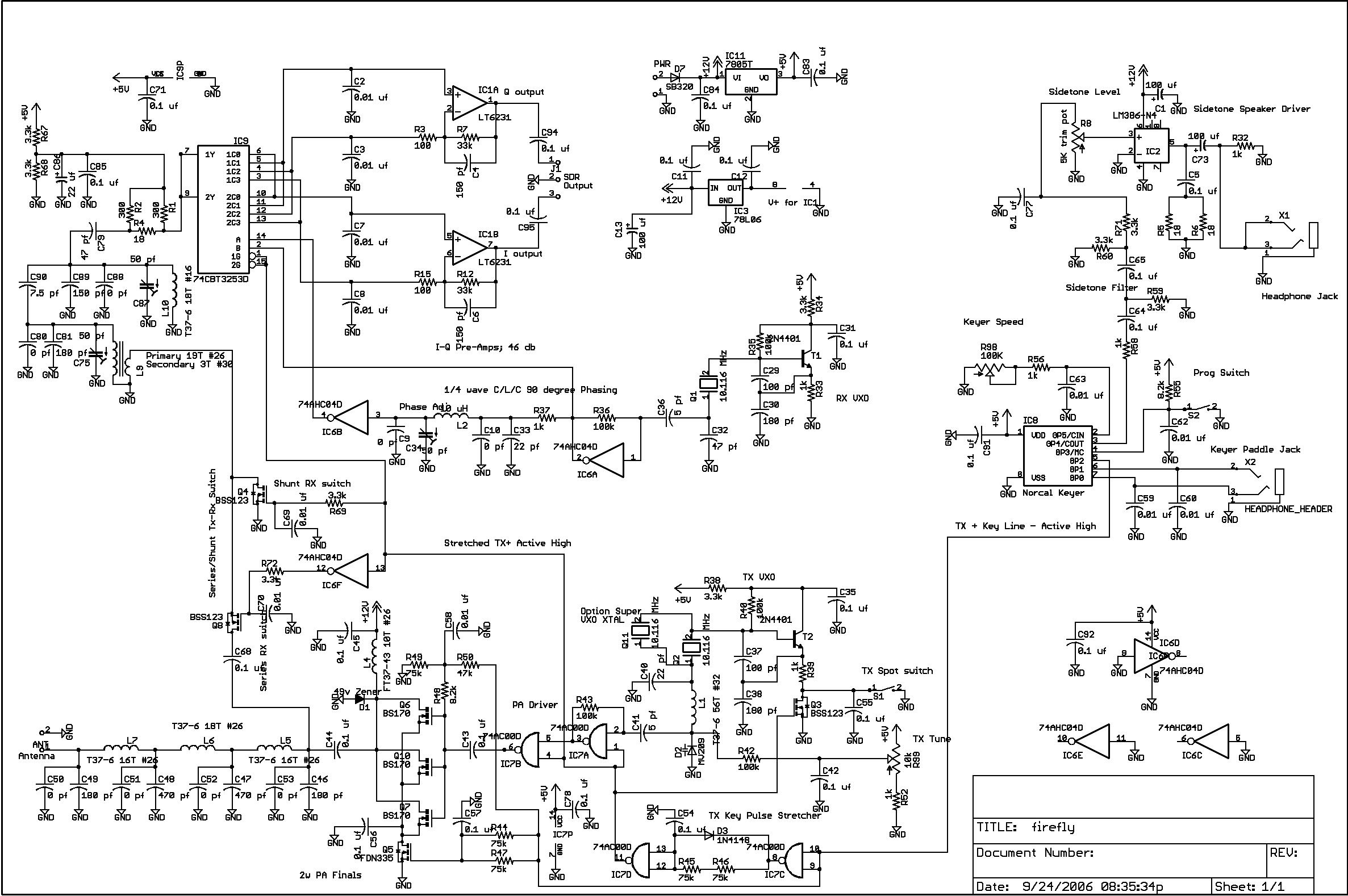
**[http://www. | *[http://www.qrpkits.com/files/SchematicsFFSDRv1-1large.JPG Firefly SDR] uses Dan Tayloe's mixer. | ||
**[http:// | *[http://www.flex-radio.com/News.aspx?topic=publications This collection of Software Defined Radio publications is fantastic.] | ||
*[http://www.sdradio.eu/sdradio/ SDRadio] | |||
**[http://www. | *[http://ra3wdk.qrz.ru/SDR.htm RA3WDK SDR Receiver (uses diode mixers)] | ||
*[http://openhpsdr.org/ Open High Performance Software Defined Radio] | |||
* | *[http://www.norcalqrp.org/files/Tayloe_mixer_x3a.pdf Tayloe Mixer] | ||
**[http:// | *[[Octave Simulation of a Tayloe Sampling Mixer]] | ||
*[http://www.m-audio.com/images/global/manuals/Delta44_Manual.pdf M-Audio Delta 44 Sound Card Manual] This manual has useful specifications for determining the gain necessary for your software designed radio project. | |||
*[http://focus.ti.com/lit/an/sloa093/sloa093.pdf Filter Design in 30 seconds] | |||
*[ | *[http://www.raltron.com/cust/tools/band_pass_filters.asp Bandpass Filter Calculator] | ||
*[http://qucs.sourceforge.net/ Quite Universal Circuit Simulator] Useful for designing and simulating circuits. Can synthesize filter circuits. | |||
*[http://www.cliftonlaboratories.com/si570_kit_from_k5bcq.htm#What_is_an_Si570_and_why_do_I_want_one What is an Si570 and why do I want one?] | |||
*[https://www.silabs.com/documents/public/data-sheets/Si5351-B.pdf The Si5351 is a good cheap programmable oscillator] with either three or eight outputs. It has pretty good phase noise. | |||
**[https://github.com/etherkit/Si5351Arduino It is used by ham radio enthusiasts with Arduino] controllors. | |||
*[http://files.radioscanner.ru/files/download/file5912/u070262.pdf First steps in Software Defined Radio (SDR)] | |||
*[http://www.ece.ucsb.edu/Faculty/rodwell/Classes/ece218b/notes/Mixer1.pdf Mixer theory] | |||
*[https://docs.google.com/viewer?url=http%3A%2F%2Fclass.ece.iastate.edu%2Fdjchen%2Fee507%2FMixer%2520Design.ppt A very nice 115 slide powerpoint presentation] on mixers from Iowa State University. It discusses metrics of mixers, and has a very nice discussion of the different types, advantages and disadvantages of each. | |||
*[http://www.qsl.net/va3iul/RF%20Mixers/RF_Mixers.pdf Theory and Comparison of Various RF Mixers] | |||
*[http://yu1lm.qrpradio.com/dc%20rx%20yu1lm.htm Serbian SDR and other radios] | |||
*[http://www.qrz.lt/ly1gp/SDR/ TinySDR and others] | |||
*[http://www.elektor.com/uploads/2011/8/50-00027.pdf Elektor SDR] | |||
*[http://whiteboard.ping.se/SDR/IQ A nice pictorial description of I/Q data] | |||
====SDR Using Realtek RTL2832U==== | |||
*[http://www.george-smart.co.uk/wiki/FunCube_Upconverter FunCube Upconverter] | |||
*[http://sdr.osmocom.org/trac/wiki/rtl-sdr The Wiki on this SDR.] | |||
*[http://www.ct1ffu.com/site/hf-converter.pdf An HF Converter for this SDR] | |||
*[http://www.reddit.com/r/RTLSDR/comments/s6ddo/rtlsdr_compatibility_list_v2_work_in_progress/ List of compatible tuners] | |||
*[http://pinouts.ru/Slots/USB_pinout.shtml USB Pinouts and Other Details] | |||
====Phase Locked Loops==== | |||
*[http://www.ece.ucsb.edu/~long/ece594a/PLL_intro_594a_s05.pdf Phase Locked Loop Circuits, S. Long, UCSB] | |||
*[http://cp.literature.agilent.com/litweb/pdf/5989-9103EN.pdf Gilbert Cell Mixers] | *[http://cp.literature.agilent.com/litweb/pdf/5989-9103EN.pdf Gilbert Cell Mixers] | ||
*[http://www.pericom.com/pdf/applications/AN047.pdf LVDS to PECL Interface] | *[http://www.pericom.com/pdf/applications/AN047.pdf LVDS to PECL Interface] | ||
*[http://www.fairchildsemi.com/an/AN/AN-780.pdf Positive Supply for ECL logic] | *[http://www.fairchildsemi.com/an/AN/AN-780.pdf Positive Supply for ECL logic] | ||
*[http://www.wenzel.com/documents/finesse.html Voltage regulators put out noise that can make for poor SDR receiver performance. Here is a clever solution. It also works for instrumentation amplifiers and other noise sensitive circuits.] | *[http://www.wenzel.com/documents/finesse.html Voltage regulators put out noise that can make for poor SDR receiver performance. Here is a clever solution. It also works for instrumentation amplifiers and other noise sensitive circuits.] | ||
*[http://fcc.gov/omd/history/radio/ Radio Development] | |||
*[http://transition.fcc.gov/pshs/techtopics/techtopics4.html Introduction to Software Defined Radio] | |||
*[http://www.wb6dhw.com/Si570/Si570.html Si570 Libraries] | |||
*[http://people.wallawalla.edu/~rob.frohne/USB_I2C/USB_I2C.zip The USB to Si570 interface design files] | |||
*[http://people.wallawalla.edu/~rob.frohne/USB_I2C/USB_I2C_schematic.svg Schematic] | |||
====Wideband Transformers==== | |||
*[http://www.electronics-tutorials.com/basics/wide-band-rf-transformers.htm Wideband Transformers] | |||
*[http://www.semelab.com/rf/documents/Push-Pull%20Circuits%20and%20Wideband%20Transformers.pdf More Wideband Transformers] | |||
*[http://home.earthlink.net/~christrask/TraskTLTTutorial.pdf Transmission Line Transformers Tutorial by Chris Trask] | |||
*[http://www.naturgrise.dk/oz9wi/artikler/HFE0204_Sevick.pdf Transmission Line Transformers, by Jerry Sevick (who wrote the book)] | |||
*[http://www.radio-kits.co.uk/radio-related/Linear_PA/ECO6907.pdf Design of HF Wideband Power Transformers] | |||
====Transformer Design==== | |||
*[http://cds.linear.com/docs/en/application-note/an39f.pdf Dealing with parasitic capacitance in step-up transformer design] | |||
*[http://ieeeb.okstate.edu/lecturenotes/EET-4654%20Microwaves/Lecture%2017%20The%20Toroidal%20Inductor.pdf Toroidal Cores] | |||
*[http://www.micrometals.com/catalog_index.html Micrometals Catalog] | |||
====Capacitors==== | |||
*[http://www.digikey.com/Web%20Export/Supplier%20Content/Murata_490/PDF/Murata_TA_Replacement_Catalog_C-24-C.pdf?redirected=1 Murata's comparison of monolithic ceramic capacitors as compared to Tantalum capacitors.] Note that monolithic ceramic capacitors values decrease if you put larger DC voltages across them though. The effective series resistance and temperature behavior are much better though. | |||
*[http://beamdream.solarbotics.net/Tutorials/CapGuide.htm The markings] on capacitors are often based on pF. There will be three digits, like 104 for 0.1uF. The first two digits are the digits of the value, and the next number is the number of zeros to add after that to denote the capacitance in pF. Thus 104 in 10 * 1e4 pF. | |||
* | ===Transmission Lines=== | ||
*Links on the [[Electromagnetic Fields/Electricity and Magnetism]] class page are useful. | |||
*[https://en.wikipedia.org/wiki/Transmission_lines Transmission Lines] | |||
*[http://www.ece.rutgers.edu/~orfanidi/ewa An entire book about electromagnetic waves and antennas is here.] | |||
=====Smith Chart===== | |||
*[http://www.fourier-series.com/rf-concepts/smithchart.html Interactive tutorials on how SMITH charts work] | |||
* | ===Vector Network Analyzer Links=== | ||
**[http:// | *[http://www.home.agilent.com/agilent/redirector.jspx?action=ref&cname=AGILENT_EDITORIAL&ckey=1000001258-1%3Aepsg%3Atcn&lc=eng&cc=US Vector Network Analyzer Basics] | ||
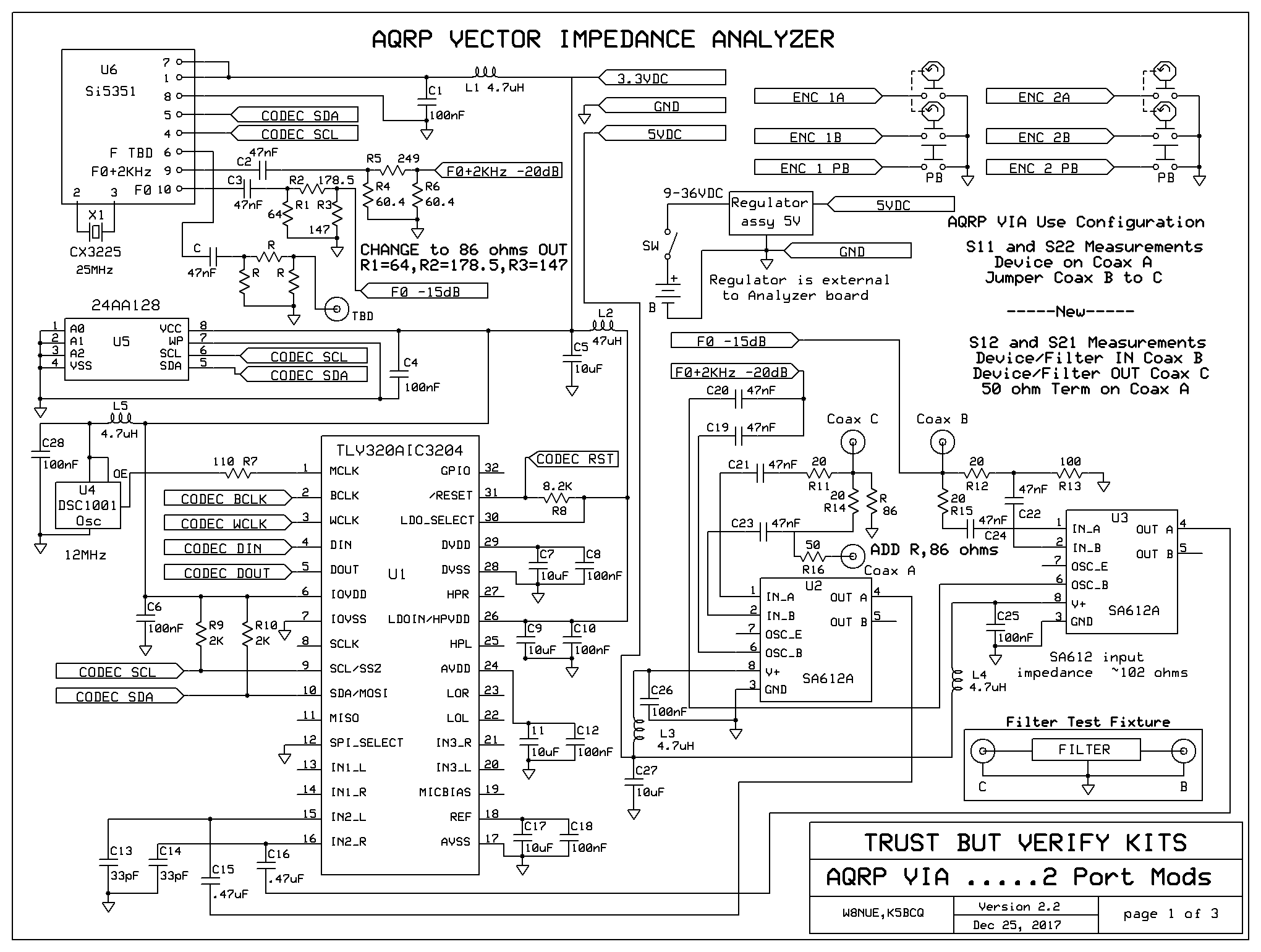
*[http://www.qsl.net/k5bcq/Kits/VIA%20User's%20Manual%20V1.00.pdf Austin QRP Club Vector Impedance Analyzer] | |||
**[http://www.qsl.net/k5bcq/Kits/VIAp1.bmp The interesting VIA schematic diagram.] More diagrams of the connections to the STM32F4 Discovery Board are on the same web site. | |||
*[http://www.rigexpert.com/index?s=articles&f=aas A short review of various antenna analyzers, and their block diagrams...] | |||
*[http://www.ece.rutgers.edu/~orfanidi/ewa/ch14.pdf A Comprehensive Chapter on S Parameters by Orfandis of Rutgers] | |||
*[[Cascading Scattering Parameters and Calibration of a VNA Using the Short, Open, Load, Through (SLOT) Method]] | |||
*[[2017 VNA Design Notes]] | |||
**[[2017 VNA Testing Software Setup]] | |||
*Kicad | ===Kicad=== | ||
**[ | ====2018 Videos Made by the Professor==== | ||
*[https://youtu.be/G6GLJbYmkpI The Kicad Project Manager, an Introduction] | |||
*[https://youtu.be/mxrdvrWgagY EESchema, the Kicad Schematic Entry Tool, an Introduction] | |||
*[https://youtu.be/rzGkvogO2x8 Adding Parts to a Schematic in Kicad] | |||
*[https://youtu.be/atXXBu0f_QU Making your own Footprint in Kicad] | |||
*[https://youtu.be/QTuSD9vxmD8 Making a new Schematic Symbol Starting from a Similar Existing Symbol in Kicad] | |||
*[https://youtu.be/KNYKaDVRTIQ Making a PCB from the schematic using Kicad PCBNew] | |||
*[https://youtu.be/7K1xT9wBxQg How to construct a 3D model for Kicad using FreeCAD and the Kicad StepUp Tool] | |||
*[https://youtu.be/XwGz29WlbBY How to import an existing 3D model from 3D Content Central for use in Kicad with FreeCAD and the Kicad StepUp workbench] | |||
====Other Kicad Links==== | |||
*[http://www.youtube.com/watch?v=rkQ0nVX1q1k Good Kicad Tutorial Video 1] | |||
*[http://www.youtube.com/watch?v=8HNMihqa844 Good Kicad Tutorial Video 2] | |||
*[http://www.kicadlib.org/Fichiers/KiCad_Tutorial.pdf KiCad Step By Step Tutorial PDF] | |||
*[http://store.curiousinventor.com/guides/kicad/ KiCad schematic and layout Guides] | |||
*[http://kicad.rohrbacher.net/quicklib.php Kicad Quick Schematic Part Creator] | |||
*[http://www.youtube.com/watch?v=xRXEc7pB0o0 KiCad Tutorial] | |||
*[http://kicad.sourceforge.net/wiki/DE:Mini_tutorial Mini Tutorial] | |||
*[http://www.youtube.com/watch?v=xRXEc7pB0o0 Installing KiCad for Windows and more video] | |||
*[http://store.curiousinventor.com/guides/kicad/schematic_to_layout/ KiCad Schematic to Layout Tutorial - CuriousInventor Guides] | |||
*[http://www.youtube.com/watch?v=Af8ez82W7_o&feature=results_video&playnext=1&list=PLE6A60D039C919B5C DPRG KiCad tutorial 3] | |||
*[http://www.youtube.com/watch?v=ls5vWSV3TlE How to design a circuit board by Doug Paradis using KiCAD] | |||
*[http://wiki.xtronics.com/index.php/Wire-Gauge_Ampacity Ampacity of Wires and Circuit Board Trace Widths]*[http://www.blackstick.co.uk/pcb-design-calculators/track-width-current-mm.php Track width for certain temperature rise Calculater] | |||
*[https://www.youtube.com/watch?v=CCG4daPvuVI A video on using the new (May 2014) push and shove router...] | |||
*[http://n8vem-sbc.pbworks.com/w/file/79819109/ABOUT-2014-05-03.txt Freerouter Java program now open source and available here.] Note that it isn't available any longer as a java applet on the web. | |||
*[http://vimeo.com/99235812 Video on using the new Module Editor] | |||
====Circuit Board Layout Hints==== | |||
*[http://people.wallawalla.edu/~Rob.Frohne/ClassHandouts/Electronics/Circuit%20Board%20Layout%20Tips%20Revised.pdf Reduce the likelihood of noise and oscillation problems.] | |||
*[http://edn.com/electronics-blogs/all-aboard-/4429390/Ten-best-practices-of-PCB-design?cid=nl_edn&elq=ee97eb731fbd4d13ac9e2c3cc18ba608&elqCampaignId=15922 Ten Best Practices of PCB Design] | |||
* Daniel Colls - Parallel traces are often susceptible to cross-talk. These should be separated by at least 2 trace widths for cross-talk reduction. when talking about Circuit Layout. | |||
* Andrew Bylard - Use a stripline circuit when you have two parallel ground planes to give enhanced noise immunity against the propagation of radiated RF emissions. | |||
*[http://www.eetimes.com/design/embedded/4211294/Tips-about-printed-circuit-board-design--Part-1---Dealing-with-harmful-PCB-effects Dealing with harmful PCB effects article] | |||
*[http://www.electronics-project-design.com/PCB-Design.html PCB Trace and Spacing Info] | |||
*[http://www.polarinstruments.com/support/cits/AP120.html Trace Impedance Matching] | |||
*[http://www.robotroom.com/PCB-Layout-Tips.html Add test points at key locations and make it easy to probe (and other tips)] | |||
*[http://www.ti.com/lit/an/szza009/szza009.pdf Make bypassing loops as small as possible in area and length (Page 10)] | |||
*[http://www.learnemc.com/tutorials/guidelines.html Some good, and some not so good EMC Design Principles] | |||
*[http://blog.screamingcircuits.com/files/top_10_issues_that_cause_bad_prototypes.pdf Common layout, prototyping, and schematic issues to avoid] | |||
*[http://www.ti.com/lit/an/slyt499/slyt499.pdf Grounding in Mixed Analog and Digital Boards part 1] | |||
*[http://www.ti.com/lit/an/slyt512/slyt512.pdf Grounding in Mixed Analog and Digital Boards part 2] | |||
**[http://www.hottconsultants.com/pdf_files/june2001pcd_mixedsignal.pdf Partitioning in Mixed Signal Boards] | **[http://www.hottconsultants.com/pdf_files/june2001pcd_mixedsignal.pdf Partitioning in Mixed Signal Boards] | ||
*[http://www.silabs.com/Support%20Documents/TechnicalDocs/AN203.pdf Silicon Labs Design Notes] | |||
*[http://www.analog.com/library/analogdialogue/archives/46-06/staying_well_grounded.pdf Staying Well Grounded] | |||
*[http://engineering.whitepapers.s3.amazonaws.com/MentorGraphics/10_Tips_for_Streamlining_82956.pdf PCB Thermal Design] | |||
**[http://electronicdesign.com/embedded/engineer-s-guide-high-quality-pcb-design The Engineer's Guide To High Quality PCB Design] | *[http://focus.ti.com/download/trng/docs/seminar/Topic%2010%20-%20Thermal%20Design%20Consideration%20for%20Surface%20Mount%20Layouts%20.pdf?DCMP=mdrvblog&HQS=gma-indu-motr-mdrvblog-150422-thermal-mc-en Thermal Design Considerations for Surface Mount Layouts] | ||
*[http://electronicdesign.com/embedded/engineer-s-guide-high-quality-pcb-design The Engineer's Guide To High Quality PCB Design] | |||
[http://www.volersystems.com/v-2010-issue-1/pcb-layout-checklist PCB Layout Checklist:] Check this before sending out your board! | *[http://www.micrel.com/_PDF/Ethernet/app-notes/an-139.pdf Some good rules of thumb are in this app note from Micrel.] | ||
*[http://irtfweb.ifa.hawaii.edu/~ao/Electronic/Peter_dump/Electronics/System/Text/PCBCADGuidelines.pdf Some good PCB guidelines considering how to approach fine pitch layout, and spacing between components, the board edges, etc.] | |||
*[http://www.volersystems.com/v-2010-issue-1/pcb-layout-checklist PCB Layout Checklist:] Check this before sending out your board! | |||
*[http://fweb.wallawalla.edu/class-wiki/index.php/Printing_and_Etching_Circuit_Boards Printing and Etching Circuit Boards] | *[http://fweb.wallawalla.edu/class-wiki/index.php/Printing_and_Etching_Circuit_Boards Printing and Etching Circuit Boards] | ||
*[[Kicad Specific PCB Hints]] | |||
===Contributors=== | |||
*2013 Contributors | |||
== | |||
#[[Eric.Wilson|Eric Wilson]] | #[[Eric.Wilson|Eric Wilson]] | ||
| Line 135: | Line 172: | ||
#[[User:Heidi.Tupper|Heidi Tupper]] | #[[User:Heidi.Tupper|Heidi Tupper]] | ||
*2012 Contributors | |||
#[[Trent Fleming|Fleming, Trent]] | #[[Trent Fleming|Fleming, Trent]] | ||
#[[Kara Moon|Kara Moon]] | #[[Kara Moon|Kara Moon]] | ||
| Line 144: | Line 181: | ||
#[[Benjamin Maloon|Benjamin Maloon]] | #[[Benjamin Maloon|Benjamin Maloon]] | ||
*2010 Contributors | |||
#[[Greg Fong|Fong, Greg]] | #[[Greg Fong|Fong, Greg]] | ||
| Line 152: | Line 189: | ||
#[[Vier, Michael]] | #[[Vier, Michael]] | ||
*2011 Contributors | |||
#[[Brian Haddad|Haddad, Brian]] | #[[Brian Haddad|Haddad, Brian]] | ||
#[[Michael von Pohle|von Pohle, Michael]] | #[[Michael von Pohle|von Pohle, Michael]] | ||
| Line 158: | Line 195: | ||
#[[Cody Lorenz]] | #[[Cody Lorenz]] | ||
==2010 Articles== | ====2010 Articles==== | ||
*[[Ideal vs. | *[[Ideal vs. Non-ideal Op Amps]] | ||
*[[Chapter 1]] | *[[Chapter 1]] | ||
*[[Chapter 2]] | *[[Chapter 2]] | ||
| Line 168: | Line 205: | ||
*[[Circuit Board Layout Wisdom]] | *[[Circuit Board Layout Wisdom]] | ||
==Draft Articles== | ====Draft Articles==== | ||
These articles are not ready for reading and error checking. They are listed so people will not simultaneously write about similar topics. | These articles are not ready for reading and error checking. They are listed so people will not simultaneously write about similar topics. | ||
| Line 175: | Line 212: | ||
*[[Reading from Chapter 4]] | *[[Reading from Chapter 4]] | ||
==Draft Articles awaiting review== | ====Draft Articles awaiting review==== | ||
*[[Feedback in Amplifiers]] | *[[Feedback in Amplifiers]] | ||
====Contributing Articles==== | |||
==Contributing Articles== | |||
*[[Generalized Transmitter]] (in progress, Luke) | *[[Generalized Transmitter]] (in progress, Luke) | ||
Latest revision as of 20:26, 18 February 2018
Links
ENGR 356 (Engineering Electronics I Class)
- What is Important, Voltage, Current or Power?
- Exam I ENGR 356 Tips
- Lab Write Up Documents
- Function Generator Manuals
- An example of a function generator manual.... This may give you a bit of an idea how to write your manual for the Function Generator Lab.
- A really simple function generator, but still a little more complicated than yours. However, you will notice the hysteresis oscillator is used in it too.
- Operational Amplifiers, Theory and Practice, by James Roberage
- Semiconductor Animations
- Common Emitter/Common Collector Amplifier Example
LTSpice
LTSpice Getting Started Guide LTSpice is a good simulator and runs on Windows, Linux (under wine), and OS X.
ENGR 357 (Engineering Electronics II Class)
Qucs Simulations
- United States Frequency Allocations
- Ceramic Capacitors Change Value with Applied Voltage and Temperature (especially small surface mount ones)
- Steve Long's and Mark Rodwell's Communications Electronics Course. See especially Steve Long's Notes at the end of the page. They are good.
- Resonators and Q This is just one of numerous interesting sets of notes from Steve Long's Notes above.
- Twin T Bandpass Filter with Adjustable Q
Software Defined Radio Links
These are also useful for the vector network analyzer project.
- R2 DSP (an early software defined radio using a dedicated DSP)
- Quadrature Signals Explained
- Jim William's very helpful video of mixers and especially I/Q ones using the Tayloe method
- Softrock and Theory
- Softrock Build Instructions and Notes
- Softrock Yahoo Interest Group
- This is a very interesting article on optimizing the performance of the Softrock radio. It is good design review of the Softrock receiver.
- Firefly SDR uses Dan Tayloe's mixer.
- This collection of Software Defined Radio publications is fantastic.
- SDRadio
- RA3WDK SDR Receiver (uses diode mixers)
- Open High Performance Software Defined Radio
- Tayloe Mixer
- Octave Simulation of a Tayloe Sampling Mixer
- M-Audio Delta 44 Sound Card Manual This manual has useful specifications for determining the gain necessary for your software designed radio project.
- Filter Design in 30 seconds
- Bandpass Filter Calculator
- Quite Universal Circuit Simulator Useful for designing and simulating circuits. Can synthesize filter circuits.
- What is an Si570 and why do I want one?
- The Si5351 is a good cheap programmable oscillator with either three or eight outputs. It has pretty good phase noise.
- It is used by ham radio enthusiasts with Arduino controllors.
- First steps in Software Defined Radio (SDR)
- Mixer theory
- A very nice 115 slide powerpoint presentation on mixers from Iowa State University. It discusses metrics of mixers, and has a very nice discussion of the different types, advantages and disadvantages of each.
- Theory and Comparison of Various RF Mixers
- Serbian SDR and other radios
- TinySDR and others
- Elektor SDR
- A nice pictorial description of I/Q data
SDR Using Realtek RTL2832U
- FunCube Upconverter
- The Wiki on this SDR.
- An HF Converter for this SDR
- List of compatible tuners
- USB Pinouts and Other Details
Phase Locked Loops
- Phase Locked Loop Circuits, S. Long, UCSB
- Gilbert Cell Mixers
- LVDS to PECL Interface
- Positive Supply for ECL logic
- Voltage regulators put out noise that can make for poor SDR receiver performance. Here is a clever solution. It also works for instrumentation amplifiers and other noise sensitive circuits.
- Radio Development
- Introduction to Software Defined Radio
- Si570 Libraries
- The USB to Si570 interface design files
- Schematic
Wideband Transformers
- Wideband Transformers
- More Wideband Transformers
- Transmission Line Transformers Tutorial by Chris Trask
- Transmission Line Transformers, by Jerry Sevick (who wrote the book)
- Design of HF Wideband Power Transformers
Transformer Design
Capacitors
- Murata's comparison of monolithic ceramic capacitors as compared to Tantalum capacitors. Note that monolithic ceramic capacitors values decrease if you put larger DC voltages across them though. The effective series resistance and temperature behavior are much better though.
- The markings on capacitors are often based on pF. There will be three digits, like 104 for 0.1uF. The first two digits are the digits of the value, and the next number is the number of zeros to add after that to denote the capacitance in pF. Thus 104 in 10 * 1e4 pF.
Transmission Lines
- Links on the Electromagnetic Fields/Electricity and Magnetism class page are useful.
- Transmission Lines
- An entire book about electromagnetic waves and antennas is here.
Smith Chart
Vector Network Analyzer Links
- Vector Network Analyzer Basics
- Austin QRP Club Vector Impedance Analyzer
- The interesting VIA schematic diagram. More diagrams of the connections to the STM32F4 Discovery Board are on the same web site.
- A short review of various antenna analyzers, and their block diagrams...
- A Comprehensive Chapter on S Parameters by Orfandis of Rutgers
- Cascading Scattering Parameters and Calibration of a VNA Using the Short, Open, Load, Through (SLOT) Method
- 2017 VNA Design Notes
Kicad
2018 Videos Made by the Professor
- The Kicad Project Manager, an Introduction
- EESchema, the Kicad Schematic Entry Tool, an Introduction
- Adding Parts to a Schematic in Kicad
- Making your own Footprint in Kicad
- Making a new Schematic Symbol Starting from a Similar Existing Symbol in Kicad
- Making a PCB from the schematic using Kicad PCBNew
- How to construct a 3D model for Kicad using FreeCAD and the Kicad StepUp Tool
- How to import an existing 3D model from 3D Content Central for use in Kicad with FreeCAD and the Kicad StepUp workbench
Other Kicad Links
- Good Kicad Tutorial Video 1
- Good Kicad Tutorial Video 2
- KiCad Step By Step Tutorial PDF
- KiCad schematic and layout Guides
- Kicad Quick Schematic Part Creator
- KiCad Tutorial
- Mini Tutorial
- Installing KiCad for Windows and more video
- KiCad Schematic to Layout Tutorial - CuriousInventor Guides
- DPRG KiCad tutorial 3
- How to design a circuit board by Doug Paradis using KiCAD
- Ampacity of Wires and Circuit Board Trace Widths*Track width for certain temperature rise Calculater
- A video on using the new (May 2014) push and shove router...
- Freerouter Java program now open source and available here. Note that it isn't available any longer as a java applet on the web.
- Video on using the new Module Editor
Circuit Board Layout Hints
- Reduce the likelihood of noise and oscillation problems.
- Ten Best Practices of PCB Design
- Daniel Colls - Parallel traces are often susceptible to cross-talk. These should be separated by at least 2 trace widths for cross-talk reduction. when talking about Circuit Layout.
- Andrew Bylard - Use a stripline circuit when you have two parallel ground planes to give enhanced noise immunity against the propagation of radiated RF emissions.
- Dealing with harmful PCB effects article
- PCB Trace and Spacing Info
- Trace Impedance Matching
- Add test points at key locations and make it easy to probe (and other tips)
- Make bypassing loops as small as possible in area and length (Page 10)
- Some good, and some not so good EMC Design Principles
- Common layout, prototyping, and schematic issues to avoid
- Grounding in Mixed Analog and Digital Boards part 1
- Grounding in Mixed Analog and Digital Boards part 2
- Silicon Labs Design Notes
- Staying Well Grounded
- PCB Thermal Design
- Thermal Design Considerations for Surface Mount Layouts
- The Engineer's Guide To High Quality PCB Design
- Some good rules of thumb are in this app note from Micrel.
- Some good PCB guidelines considering how to approach fine pitch layout, and spacing between components, the board edges, etc.
- PCB Layout Checklist: Check this before sending out your board!
- Printing and Etching Circuit Boards
- Kicad Specific PCB Hints
Contributors
- 2013 Contributors
- Eric Wilson
- Michael Swan
- Alexander Beckner
- Brian Clark
- Brian Lenz
- Travis deFluiter
- Tobias
- Heidi Tupper
- 2012 Contributors
- 2010 Contributors
- 2011 Contributors
- Haddad, Brian
- von Pohle, Michael
- Blaire, Matthew (Included in my name tag is Experimentation with LTspice)
- Cody Lorenz
2010 Articles
- Ideal vs. Non-ideal Op Amps
- Chapter 1
- Chapter 2
- Basic Op Amp circuits
- Key Facts from Reading Chapter 1
- Golden Rules
- Integrator_Amplifier (by Ben)
- Circuit Board Layout Wisdom
Draft Articles
These articles are not ready for reading and error checking. They are listed so people will not simultaneously write about similar topics.
- Chapter 3 Problems by Ben
- Disecting an Instrumentation Amplifier via Superposition
- Reading from Chapter 4
Draft Articles awaiting review
Contributing Articles
- Generalized Transmitter (in progress, Luke)
- Generalized Receiver (in progress, Luke)
- Electronics Receiver (in progress, Kevin)
- Generalized Receiver (Nick Christman)
- Generalized Receiver Explanation (Jodi Hodge)
- Eric's Generalized Receiver Explanation (Eric Clay)
- Yet another Generalized Receiver Explanation (Joshua Sarris)