An Ideal Transformer Example: Difference between revisions
Jump to navigation
Jump to search
| (2 intermediate revisions by one other user not shown) | |||
| Line 21: | Line 21: | ||
<math>=(\frac{N_{1}}{N_{2}})^2{Z_{L}}</math> | <math>=(\frac{N_{1}}{N_{2}})^2{Z_{L}}</math> | ||
Now, | Now, plugging in the given values: | ||
<math>\ {Z_{th}} = 3^2(5+j3)</math> | <math>\ {Z_{th}} = 3^2(5+j3)</math> | ||
| Line 27: | Line 27: | ||
<math>\ =(45+j27)\Omega</math> | <math>\ =(45+j27)\Omega</math> | ||
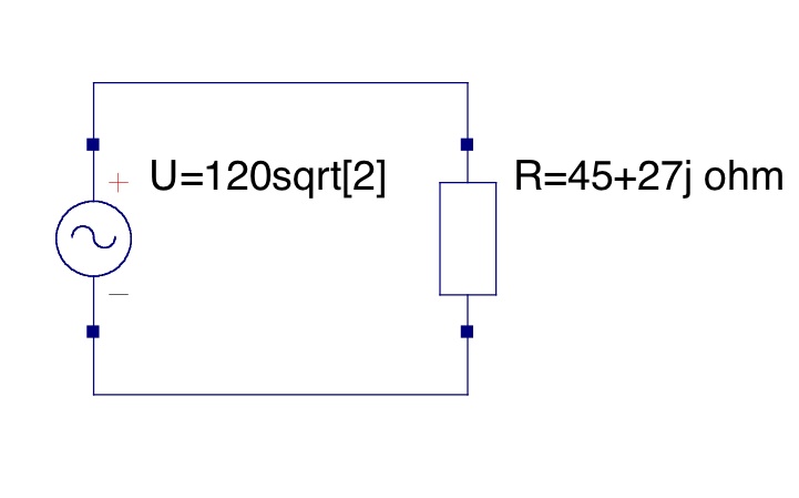
Since <math>{i_{1}}=\frac{e_{1}}{Z_{th}}</math>, | Since this is an ideal transformer, it can be modeled by this simple circuit: | ||
[[Image: Ideal_Circuit.jpg]] | |||
Therefore, <math>{i_{1}}=\frac{e_{1}}{Z_{th}}</math>, | |||
<math>{i_{1}}=\frac{120\sqrt{2}}{45+j27} A</math> | <math>{i_{1}}=\frac{120\sqrt{2}}{45+j27} A</math> | ||
===Contributors=== | ===Contributors=== | ||
| Line 40: | Line 40: | ||
===Reviwed By=== | ===Reviwed By=== | ||
Andrew Sell - Chris, everything looks fine, though I would do some extra formatting if possible to help make the problem flow a little smoother as you read it, and locate the picture a little higher to help bring the solution together. | Andrew Sell - Chris, everything looks fine, though I would do some extra formatting if possible to help make the problem flow a little smoother as you read it, and locate the picture a little higher to help bring the solution together. | ||
Tyler Anderson - Looks good. | |||
===Read By=== | ===Read By=== | ||
John Hawkins | John Hawkins | ||
Latest revision as of 16:34, 24 January 2010
Consider a simple, transformer with two windings. Find the current provided by the voltage source.
- Winding 1 has a sinusoidal voltage of ° applied to it at a frequency of 60Hz.
- The combined load on winding 2 is
Solution
Given: and
Substituting ,
Therefore,
Now the Thevenin equivalent impedance, , is found through the following steps:
Since this is an ideal transformer and
So we can substitute,
Now, plugging in the given values:
Since this is an ideal transformer, it can be modeled by this simple circuit:

Therefore, ,
Contributors
Reviwed By
Andrew Sell - Chris, everything looks fine, though I would do some extra formatting if possible to help make the problem flow a little smoother as you read it, and locate the picture a little higher to help bring the solution together.
Tyler Anderson - Looks good.
Read By
John Hawkins