Christman GeneralizedReceiver: Difference between revisions
No edit summary |
No edit summary |
||
| Line 5: | Line 5: | ||
<center>[[Image:HW2_GenTran.jpg]]</center> | <center>[[Image:HW2_GenTran.jpg]]</center> | ||
<br/> | <br/> | ||
As can be seen from the figure above, in order to transmit <math>m(t)</math>, one must first process the data using a baseband processor (usually accomplished with software). As a result of this process the original data will be split into two signals, <math>x(t)</math> and <math>y(t)</math>, and shifted to a frequency <math>f_c</math> (and <math>-f_c</math> because of the notion of a complex conjugate). Note that the original wireless communication data that you want to send is in the form known as | As can be seen from the figure above, in order to transmit <math>m(t)</math>, one must first process the data using a baseband processor (usually accomplished with software). As a result of this process the original data will be split into two signals, <math>x(t)</math> and <math>y(t)</math>, and shifted to a frequency <math>f_c</math> (and <math>-f_c</math> because of the notion of a complex conjugate). Note that the original wireless communication data that you want to send is in the form known as ''baseband'', which consists of frequencies near D.C. (or <math>f_c = 0</math>). When you actually send the communication data, however, you want to send it via much higher frequency (one which is inaudible to humans) and this creates a ''bandpass'' signal. This concept is illustrated below: | ||
<br/> | <br/> | ||
| Line 11: | Line 11: | ||
<br/> | <br/> | ||
How is the data split and shifted you ask? Mathematically speaking, in the world of "Communication Systems" a signal to be transmitted can be written as | |||
<br/> | <br/> | ||
<center> | <center> | ||
<math>\displaystyle v(t) = Re[g(t) \cdot e^{j\ | <math>\displaystyle v(t) = Re[g(t) \cdot e^{j(\omega_c t)}]</math>, | ||
</center> | </center> | ||
<br/> | <br/> | ||
where <math>g(t) = x(t) + jy(t)</math> is the signal to be sent and <math>\scriptstyle e^{j\omega_{c}t} = \cos{\ | where <math>g(t) = x(t) + jy(t)</math> is the signal to be sent and <math>\scriptstyle e^{j\omega_{c}t} = \cos{(\omega_c t)} + j\sin{(\omega_c t)}</math> (Euler's identity) shifts the signal in the frequency domain by <math>\omega_{c} = 2 \pi f_{c}</math>. | ||
<br/> | <br/> | ||
The above formula can then be rewritten to obtain the following relationship: | The above formula can then be rewritten to obtain the following relationship: | ||
| Line 25: | Line 25: | ||
<center> | <center> | ||
<math>\displaystyle v(t) = Re[g(t) \cdot e^{j\omega_{c}t}] = Re[(x(t) + jy(t)) \cdot (\cos{\ | <math>\displaystyle v(t) = Re[g(t) \cdot e^{j\omega_{c}t}] = Re[(x(t) + jy(t)) \cdot (\cos{(\omega_c t)} + j\sin{(\omega_c t)})] = x(t)\cos{(\omega_c t)} - y(t)\sin{(\omega_c t)}</math>. | ||
</center> | </center> | ||
<br/> | <br/> | ||
As you can also from the above relationship, in order to obtain the appropriate output signal <math>v(t)</math> one must multiply <math>x(t)</math> by a cosine function and <math>y(t)</math> by a negative sine function and then sum the results (this is illustrated in the figure above). In simplified terms and details, this is essentially how the data <math>m(t)</math> is transmitted. | |||
<br/> | <br/> | ||
The process of receiving data, <math>m(t)</math>, via a wireless signal, <math>v(t)</math>, is shown below: | Receiving the original data from a wireless signal is very similar to that of transmitting the data (as described before). The process of receiving data, <math>m(t)</math>, via a wireless signal, <math>v(t)</math>, is shown below: | ||
<center>[[Image:HW2_GenRec.jpg]]</center> | <center>[[Image:HW2_GenRec.jpg]]</center> | ||
In short, the data that we are interested in (<math>m(t)</math>) is embedded within the carrying signal (<math>v(t)</math>) which is at a frequency inaudible to human ears. Thus, in order to get the original communication data it is necessary to somehow bring the bandpass signal back down to its original baseband form -- and this is what the second quarter of electronics is all about. | |||
If you have not already discovered, to recover the original data <math>x(t)</math> and <math>y(t)</math> from the signal signal <math>v(t)</math> we must perform a task known as "mixing" and then run the results through low pass filters. Simply put, we need to multiply <math>v(t)</math> by <math>\cos{(\omega_c t)}</math> and <math>-\sin{(\omega_c t)}</math>. To see this mathematically, recall that <math> v(t) = x(t)\cos{(\omega_c t)} - y(t)\sin{(\omega_c t)} </math>. Therefore, | |||
<center> | |||
<math>\cos{(\omega_c t)} \cdot v(t) = cos{(\omega_c t)} \cdot [x(t)\cos{(\omega_c t)} - y(t)\sin{(\omega_c t)}] = x(t)\cos^{2}{(\omega_c t)} - y(t)\cos{(\omega_c t)}\sin{(\omega_c t)}</math> | |||
</center> | |||
But when <math>\cos{(\omega_c t)}\sin{(\omega_c t)}</math> is ran through a low pass filter it is filtered out, whereas <math>\cos^{2}{(\omega_c t)}</math> is not; therefore, we are left with <math>x(t)</math> as desired! (Similarly, <math>y(t)</math> can be obtained.) | |||
Revision as of 20:03, 8 April 2010
How It Works: Generalized Receiver
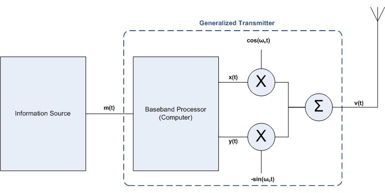
The process of transmitting data, , via a wireless signal, , is shown below:

As can be seen from the figure above, in order to transmit , one must first process the data using a baseband processor (usually accomplished with software). As a result of this process the original data will be split into two signals, and , and shifted to a frequency (and because of the notion of a complex conjugate). Note that the original wireless communication data that you want to send is in the form known as baseband, which consists of frequencies near D.C. (or ). When you actually send the communication data, however, you want to send it via much higher frequency (one which is inaudible to humans) and this creates a bandpass signal. This concept is illustrated below:

How is the data split and shifted you ask? Mathematically speaking, in the world of "Communication Systems" a signal to be transmitted can be written as
,
where is the signal to be sent and (Euler's identity) shifts the signal in the frequency domain by .
The above formula can then be rewritten to obtain the following relationship:
.
As you can also from the above relationship, in order to obtain the appropriate output signal one must multiply by a cosine function and by a negative sine function and then sum the results (this is illustrated in the figure above). In simplified terms and details, this is essentially how the data is transmitted.
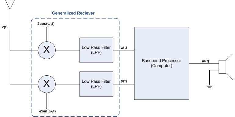
Receiving the original data from a wireless signal is very similar to that of transmitting the data (as described before). The process of receiving data, , via a wireless signal, , is shown below:

In short, the data that we are interested in () is embedded within the carrying signal () which is at a frequency inaudible to human ears. Thus, in order to get the original communication data it is necessary to somehow bring the bandpass signal back down to its original baseband form -- and this is what the second quarter of electronics is all about. If you have not already discovered, to recover the original data and from the signal signal we must perform a task known as "mixing" and then run the results through low pass filters. Simply put, we need to multiply by and . To see this mathematically, recall that . Therefore,
But when is ran through a low pass filter it is filtered out, whereas is not; therefore, we are left with as desired! (Similarly, can be obtained.)