Electronics Receiver
Electronics Receiver Explanation:
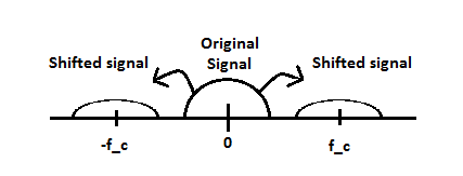
When a Signal is transmitted they take the original baseband m(t) signal and send it through a bandpass processor that splits the signal into a real (x(t)) and an imaginary (y(t)) parts and then shifts the signal to +/- a designated frequency by mixing the signals with cos(w_c*t) for x(t) and -sin(w_c*t) for y(t). This is shown math mathematically below where v(t) is the output signal and w_c is the amount shifted.
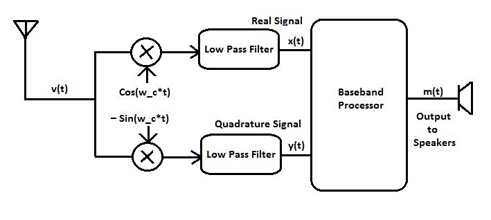
The purpose of your receiver is to retrieve this signal. This is done by first taking the transmitted signal and mixing it with cos(w_c*t)(to get x(t) and -sin(w_c*t) (to get y(t) also referred to as the quadrature signal) and filtering those two signals using a low pass filter. After you have those signals you can send them through a baseband processor (in the computer in this case) and it will process the signal and send the results to your speakers.

