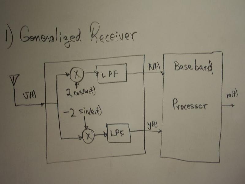
Generalized Receiver Explanation
Human voice is heard near DC frequencies and is well suited to be packaged in a baseband signal. If a baseband signal is needed to be transmitted, the generalized transmitter will transform the baseband signal into a band pass signal, which has the benefit of requiring only half as much power. After the signal has been transmitted, the job of the generalized receiver is to transform the band pass signal, use for transmitting, back to the original base band signal. Circuit elements needed to create the generalized receiver are an oscillator, two low-pass filters, and two multipliers.

Experimental
Like what you will do in lab, to create a band pass signal will include the following stages.
Stage one [Oscillator] From your oscillator, manipulate the output take two signals; one that is twice the amplitude of the output and another that is twice the amplitude, inverted, and phase shifted by 90 degrees. As seen in the picture, this is the signals.
Stage two [Mixers] Lets call the band pass input into the receiver . Lets call the base band signal Failed to parse (syntax error): {\displaystyle g=x(t)+iy(t)<math>, where the two outputs of the receiver are its real and imaginary components. Mixers work as multipliers. So the next step in building your general receiver is to use your mixers to perform multiplication of your input with your oscillator. Since we need two separate outputs, let’s have one mixer perform the multiplication of the band pass signal with cosine and the other mixer to perform the multiplication of the band pass signal with negative sine. Stage three [Low pass filters] The next stage in your receiver is to send the output of the multipliers into low pass filters (LPF). The LPF bandwidth is near to the frequency of the oscillator which will cut off all other frequencies we do not want. ---- '''Theoretical''' Theoretically, this how your convert a base band signal to a band pass signal. The band pass signal <math>=y(t)\!} is the real part of the result of the complex baseband signal .
and components of the original baseband signal.
This is the calculation that shows how the band pass signal, the oscillator, and the low pass filter are used.
The value of is substituted in
Multiplication distribution is performed
Trigonometry identities are used
The low pass filter is used to remove frequencies above wc, in this case all the terms with 2wc
The only signal that remains after the low pass filter is
The same manipulation is done to get but rather than multiply the input by it is multiplied by